AMETEK CTS Quick start guide - Conducted
1.00 12 / 50
3. Safety functions
The test area must be organized so that only those involved in the test may enter it. In the case that the safety circuit is used
to control the complete area, an additional interlock contact must be used to directly protect the operator from contact with the
DUT.
Neither the DUT nor any cables or accessories must be touched during the test. During work on the DUT, the test procedure
must be stopped and the DUT disconnected from the power mains supply.
Coupling devices have no safety functions built in, because these functions are integrated in the generators.
3.1. Safety circuit
The safety circuit will switch off the high voltage and the TEST
ON button of the unit.
3.1.1. Safety circuit for compact NX and NSG 3000A series
The safety circuit locks the system and enables the generation of
the high voltage impulses in the generators.
Design
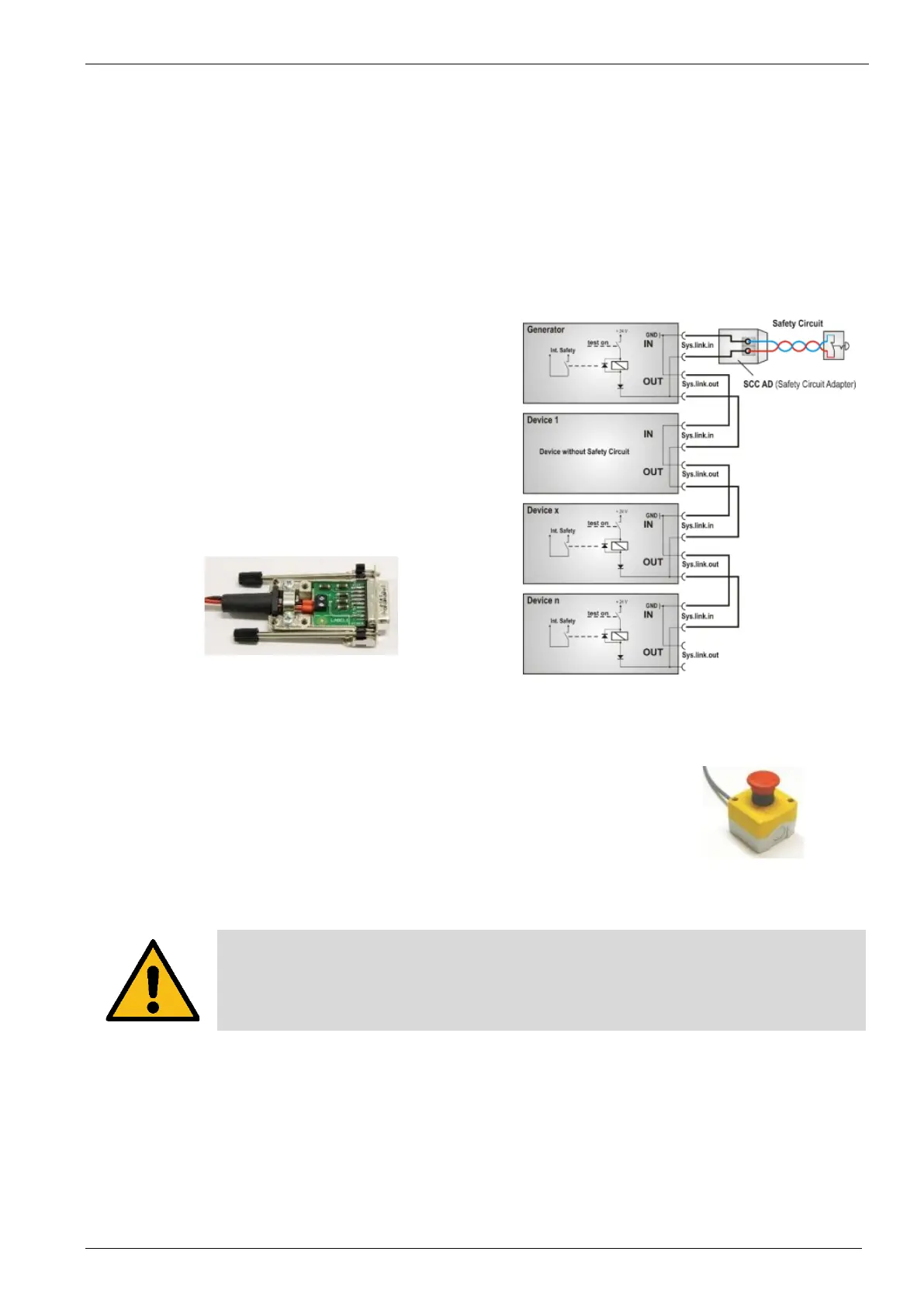
Each device that has internal relevant high voltage unit, includes a
safety circuit. The safety circuit works like an “open collector
circuit”, where the external safety loop must be closed for switch
on the high voltage.
Safety circuit closed
The device will generate high voltage pulses after start
Safety circuit open
The device will switch off the high voltage and discharges the high
voltage circuit
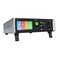
Figure 9 - Safety Circuit
Figure 10 - Safety Circuit Diagram
3.1.2. Safety circuit on Rack Systems
Rack Systems have a separate safety circuit, driven by the mains supply voltage.
Release the Safety Circuit button will disconnect the mains power from the devices and
EUT supply.
For power on it is necessary to unlock the red colored safety button manually by turning.
Figure 11 - Rack Stop Button
National Standards for safety circuits can differ from the example above.
The user is responsible for the correct design of his safety circuit.
 Loading...
