AMETEK CTS Quick start guide - Conducted
1.00 46 / 50
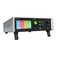
1 Insulating plate
2 Indication Protected side
4 Earth plugs
5 Indication Unprotected side
6 Output Port EUT via coupling/decoupling network
11.7. General
Coupling of the surge pulses is achieved by means of the coupling / decoupling network HSC 4-8. For additional protection of the
auxiliary equipment by reducing the residual voltage level the SPN 508N1 is used.
The HSC 4-8 design is based on the IEC 61000-4-5 (Ed 3.0: 2012) figure 11, IEC 61000-4-12 (Ed. 3) figure 10.
The HSC 4-8 allows the following couplings with separate input connectors:
- Surge and Ring wave pulses to data-lines
- Surge pulses to shield
- Burst pulses to shield
For an additional overvoltage protection of the AE port the SPN 508N2 can be used for limiting the residual voltage to approx. 10V.
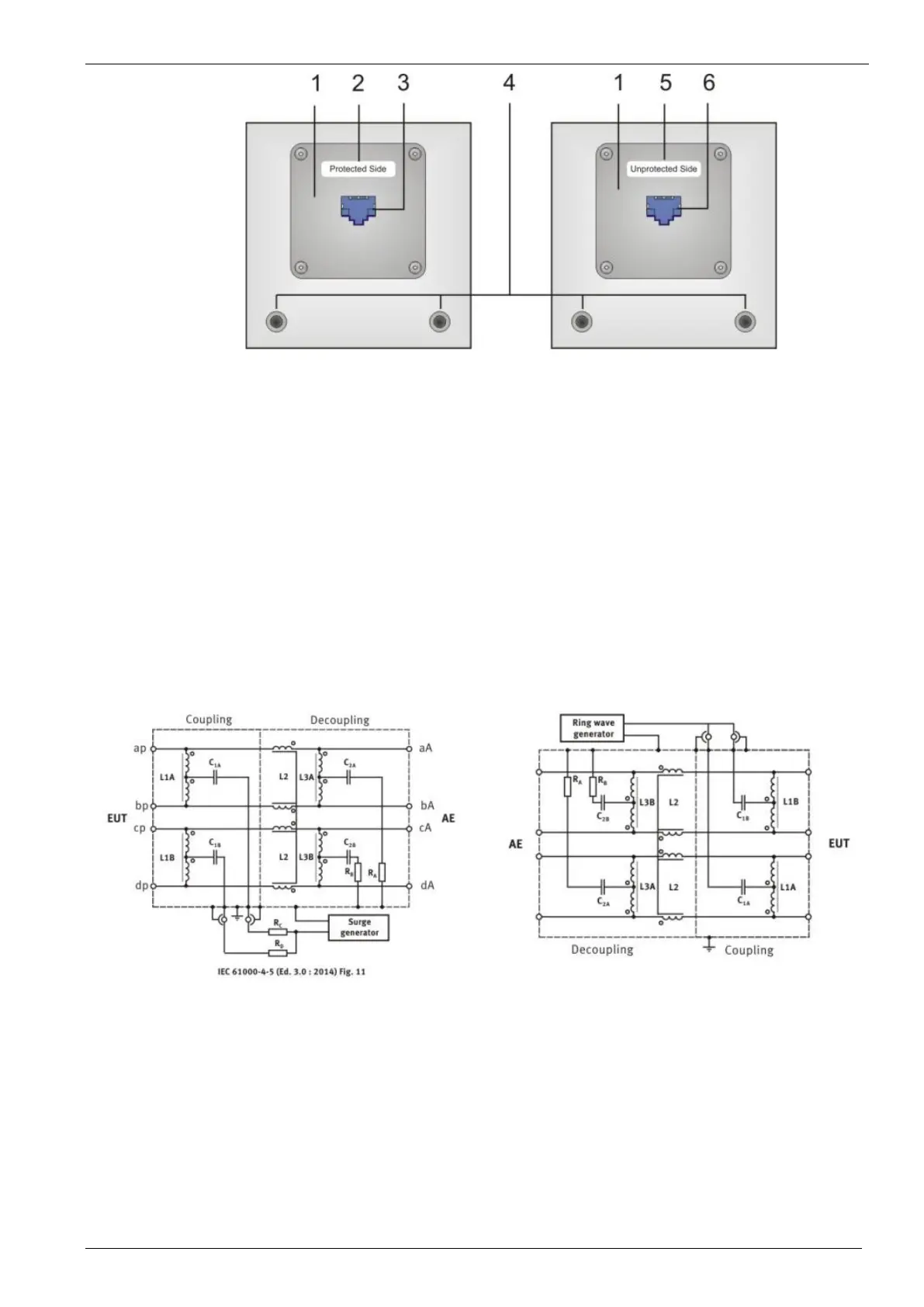
Figure 63 - Schematic of the HSC 4-8 for Surge to high speed
data-lines
Figure 64 - Schematic of the HSC 4-8 for Ring Wave to high
11.8. Test methods for Surge and Ring Wave to high speed datalines
The IEC 61000-4-5 Ed.3 Surge standard shows in figure 11 the coupling network for testing high speed datalines.
The solution for coupling/decoupling is based on the existing methods of surge testing. There are two different Methods for testing
surge pulses on datalines.
Coupling to shielded lines