AMETEK CTS Quick start guide - Conducted
1.00 33 / 50
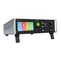
Figure 35 - Front side connections
1. BCC 350, Burst connection cable. Coaxial cable for connect the EFT
Burst pulse from the generator to the coupling.
2. Burst output to a capacitive coupling clamp CCI with the coaxial
connection cable BCC 1000.
3. Output to the EUT. Burst and Surge pulses are coupled to the supply
lines.
4. Surge output to external CDN for data lines via a HVS cable.
Figure 6.2: Front side compact NX5 with coupling NX5
Figure 36 - Rear side connections
1. Copper braid for earth the generator and coupling
2. HVS Surge cable
3. SCC AD, Safety circuit Adapter (Sys.link)
4. SLC 500 Sys.Link cable (Daisy chain)
5. SWL AD, Safety warning Lamp Adapter (Sys.link)
6. Mains supply (control)
7. EUT supply input
8. Earth connection to reference ground plane with low inductance
connection.
Figure 6.3: Rear side compact NX5 with coupling NX5
8.4. Connecting CDN 30x3A-C32 with NSG 30x0A generator
When setting up the test national and international regulations regarding human safety have to be guaranteed.
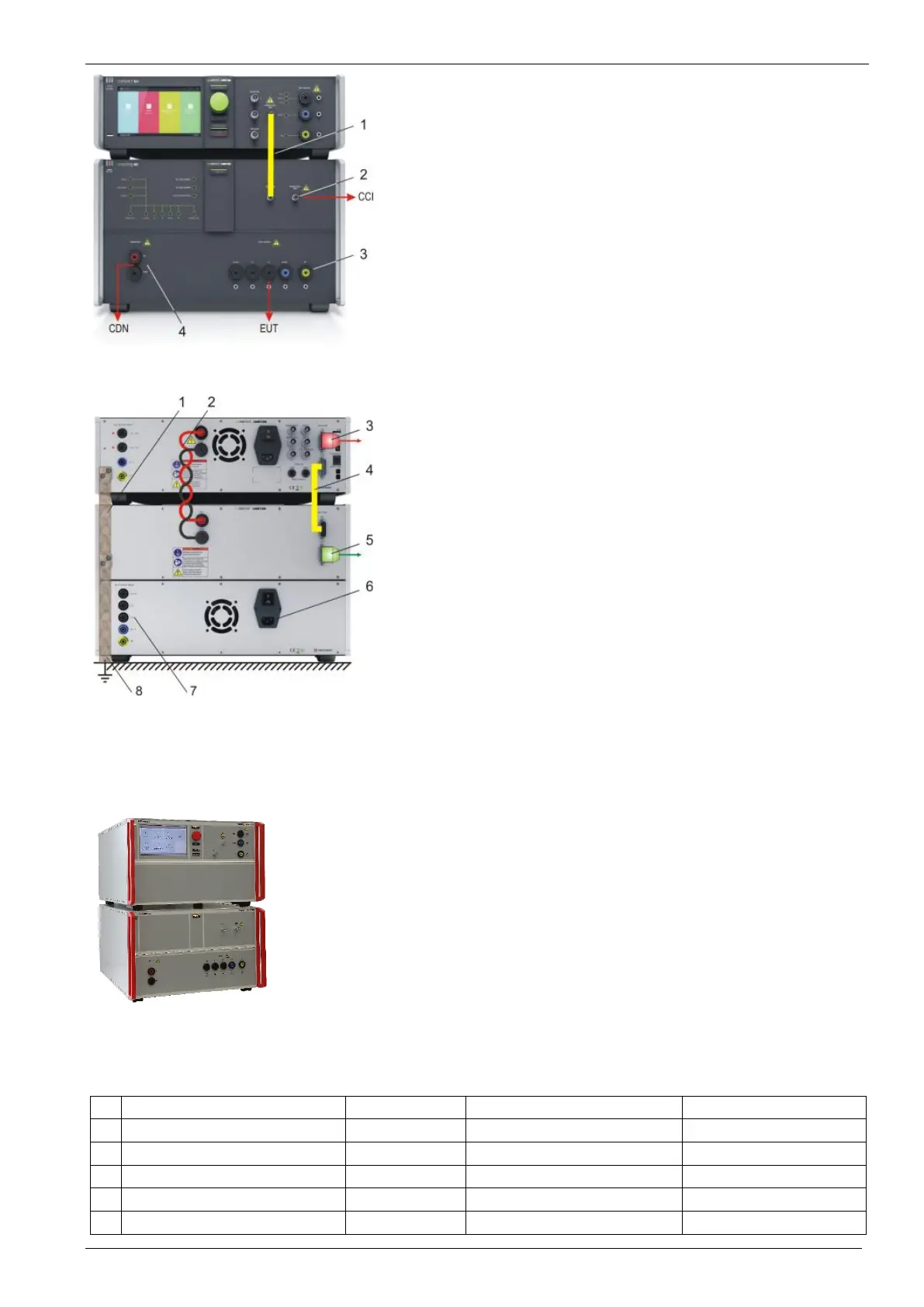
Figure 37 - Example Test
All units, the surge generator, the EFT and the coupling matrix can be installed one above the other.
The coupling network should be used as central output for the EUT and should be mounted
directly onto the ground reference plane.
The NSG 3060A has to be mounted directly above the CDN 3063A-C32 due to the short HV cable.
It is recommended to connect the simulator to the ground reference plane of the test set-up.
Figure 3.1: Example of a test rack with NSG 3060A and CDN 3063A-C32
Connect the following cables between the generator and coupling network
Name Length [m] Connection Remark
1 SLC 500, Sys Link cable 0.5 m, (1.0 m) NSG 3060A – CDN 3063A
26 pole D-Sub High Density
2 BCC 350, HVS Burst cable 0.4 m NSG 3060A – CDN 3063A
3 HVS Surge cable 0.5 m NSG 3060A – CDN 3063A 2 cable for HV and COM
4 Earth connection 0.3 m NSG 3060A – CDN 3063A 300 mm x 23 mm; 25 mm
2
5 Earth connection 0.3 m CDN 3063A – Ref GND 300 mm x 23 mm; 25 mm
2
 Loading...
