AMETEK CTS Quick start guide - Conducted
1.00 25 / 50
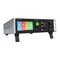
6.8. Rear view (model-specific distinctions)
1 Phase indication PF1 / PF2
2 EUT supply input
3 Surge output HV - COM
4 Ventilator
5 Mains Switch
8 Fail, EUT 1, EUT2
9 External Trigger IN
10 Sys Link IN
11 USB A interface
14 Opto Link Interface
15 Sys Link OUT
16 Sync input
17 Mains input device
18 Reference earth connection
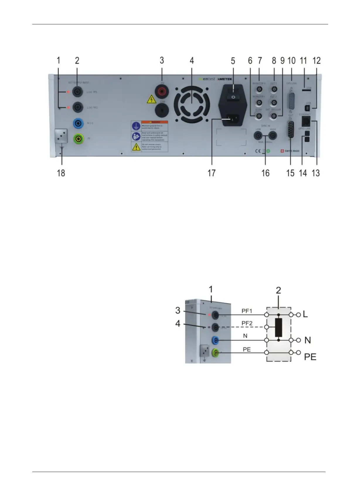
6.9. Phase indicator (compact NX-models only)
The phase indication shows the correct connection of the supply to Phase and Neutral input of the compact NX . For the
generator hardware, both, L and N paths are potential free and a reverse connection is not relevant for the generator
operation. It is in the responsibility of the user to decide to run the test in correct phase-neutral connection. Anyway, with
wrong phase connection it is possible and normal to measure a voltage between neutral and earth.
1 compact NX5 generator
2 EUT supply may be a
- direct supply from building or via a
- tapped or variac transformer
3 Phase indication LED illuminated
4 Phase indication LED inactive
Note: The phase synchronization signal taken from the L
path.
Figure 28 - Phase Indication
6.10. Power ON the compact NX - NSG 3000A generator
Approx. 3-4 seconds after power on the generator will drive the ventilator at full speed during few seconds. Then the
ventilator returns to a variable speed control concerning the temperature.
Booting
After the welcome screen the software scans the equipment for search all existing internal phenomenon’s and external
devices. A list shows and lists all detected modules.
 Loading...
