AMETEK CTS Quick start guide - Conducted
1.00 32 / 50
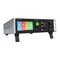
8.2. Mains Switch and fuse
The mains power voltage indicated on the instrument must correspond with the local supply voltage (mains voltage: 85–265
Vac, universal power unit, mains frequency: 50–60 Hz).
Figure 33 - Mains Switch, fuse holder and power
input
1) Disconnect the mains cable
2) Pull the fuse holder out of the connector
3) Remove the damaged fuse(s)
4) Insert 2 fuses, (2 x 2 A / 230 V slow blow)
5) Replace the fuse holder
6) Plug the mains cable into a power outlet with a solid ground
connection
7) Switch the system on and operate as instructed in this manual
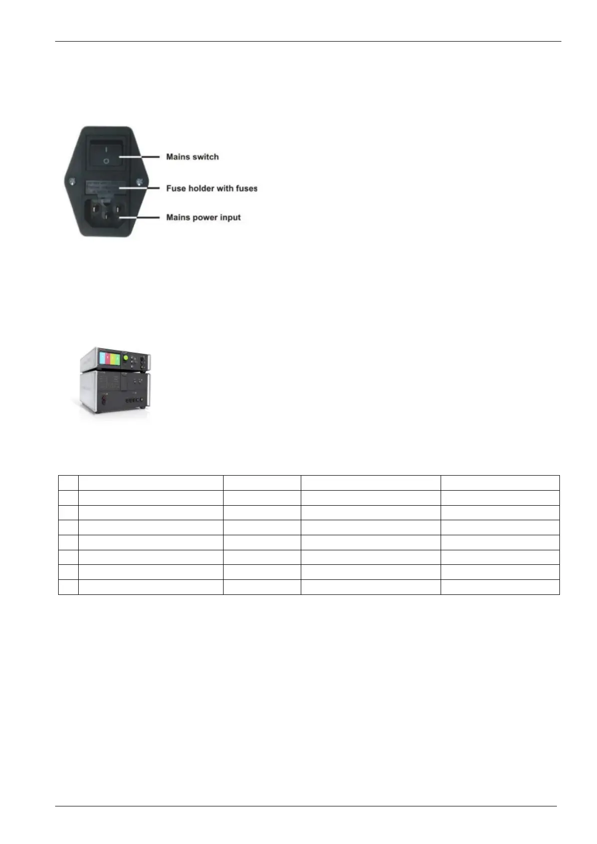
8.3. Connecting coupling NX with compact NX generator
When setting up the test national and international regulations regarding human safety have to be guaranteed.
Figure 34 - Adding coupling
All units, the surge generator, the EFT and the coupling matrix can be installed one above the other.
The coupling matrix should be used as central output for the EUT and should be mounted
directly onto the ground reference plane.
The compact NX5 has to be mounted directly above the coupling NX5 due to the short HV cable.
It is recommended to connect the simulator to the ground reference plane of the test set-up.
Figure 6.1: Example of a test rack with compact NX5 and coupling NX5 bs-3-480-16
Connect the following cables between the generator and coupling network
Name Length [m] Connection Remark
1 SLC 500, Sys Link cable 0.5 m, (1.0 m) compact NX5 – coupling NX
26 pole D-Sub High Density
2 BCC 400, HVS Burst cable 0.4 m compact NX5 – coupling NX
3 HVS Surge cable 0.5 m compact NX5 – coupling NX
4 Earth connection 0.3 m compact NX5 – coupling NX 300 mm x 23 mm; 25 mm
2
5 Earth connection 0.3 m coupling NX – Ref GND 300 mm x 23 mm; 25 mm
2
6 Power mains cable 2 m Mains – Supply coupling 85V to 154 V 50 / 60 Hz
7 EUT mains To define Mains 3-ph – EUT input Ext fuse required