AMETEK CTS Quick start guide - Conducted
1.00 41 / 50
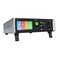
9.8. Coupling network DCD st, 8 lines
Each of the 8 lines has an impedance of= 320 Ω
Figure 51 - 320 Ω, 8 Lines
Two lines are switched in parallel. Each of the 4 lines has an
impedance of= 160Ω (320 Ω // 320 Ω)
L1 = (L1’ // L5’)
L2 = (L2’ // L6’)
L3 = (L3’ // L7’)
L4 = (L4’ // L8’)
Figure 52 - 160 Ω, 4 Lines
Four lines are switched in parallel. Each of the 2 lines has an
impedance of= 80Ω (320 Ω // 320 Ω // 320 Ω // 320 Ω)
L1 = (L1’ // L3’ // L5’ // L7’)
L2 = (L2’ // L4’ // L6’ // L8’)
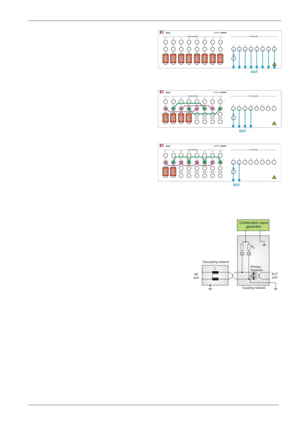
9.9. Test setup for 10/700 µs impulses
Due to the nature of the wiring used for unshielded outdoor symmetrical
communication lines (twisted pairs), the coupling is always in common mode.
The coupling decoupling schematic is shown in Figure A.4. (IEC 61000-4-5 Ed
3.0)
Coupling via arrestors(GDT) or Avalanche breaking diodes (ABD) is the
preferred coupling method for unshielded outdoor symmetrical communication
lines. The coupling network also has the task of splitting the surge current into
multiple pairs in multi-conductor cables. The internal generator matching
resistor Rm2 (25 Ω) is replaced by the Rc = 25 Ω in the DCD coupling /
decoupling network.
Figure 54 - IEC 61000-4-5 Ed3.0