AMETEK CTS Quick start guide - Conducted
1.00 14 / 50
3.3. Earthing of devices
Generators must be grounded to the reference ground plane. Generally, the generators
are equipped with an aluminum earth bolt (8x30mm) at the rear side of the device.
For contact the earth bolt there are the following connections:
- Screw M4 x 12 mm tapped hole
- Ø 4mm x 20mm holes for 4mm banana plugs
The drawing shows the dimensioning of the earth bolt.
Figure 16 - Earth Connection
Earth connection with a tress
The earth connection must be designed as a low ohmic and low inductance connection
as illustrated as example in the picture at the right side.
This solution allows the user for fast exchange the device.
Figure 17 - Earth Connection
Earth connection with a brass bar
Alternative method is using a brass bar equipped with banana plugs and additional fixed
with a M4 screw as illustrated at the right-side picture.
This is a solution preferred for fix mounted test setup installation.
Figure 18 - Earth with Brass Bar
3.4. FI Fault current protection
The standards recommend decoupling and filter capacitors to PE for decoupling surge pulses. This is the reason for tripping
fault current protection relays interrupt the mains to the EUT supply. For eliminate the circumstance use one of the following
options:
Remove the fault current protection
This solution does not limit the current to PE. The surge test as other EMC tests with higher currents to PE are possible. The
user must take care to the circuit with no fault current protection. Only trained professional people are allowed to perform such
tests.
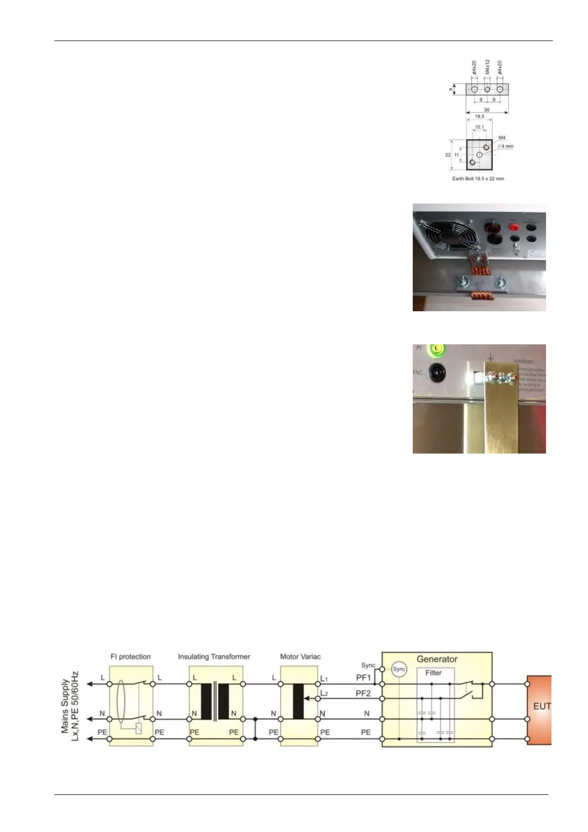
Using of insulating transformers
An insulating transformer separates the circuit from the protected path. The synchronization works between line and PE and
therefore a connection between neutral and PE is necessary. Without this connection the stray capacitance defines the phase
sync.
Figure 19 - Example with Insulating Transformers
Behind the insulating transformer the neutral and PE must be connected for a proper phase synchronization of the generator.
In case of a 3-phase system the user must perform similar.
 Loading...
