AMETEK CTS Quick start guide - Conducted
1.00 40 / 50
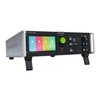
9.6. Coupling to GND
9.6.1. Test setup Coupling to PE
Figure 48 - Example for coupling as per IEC 61000-4-5
Coupling: Capacitive with 0.5 µF and 40 Ω resistor
Coupling Path: Line L1 (S2) protected earth PE (S1)
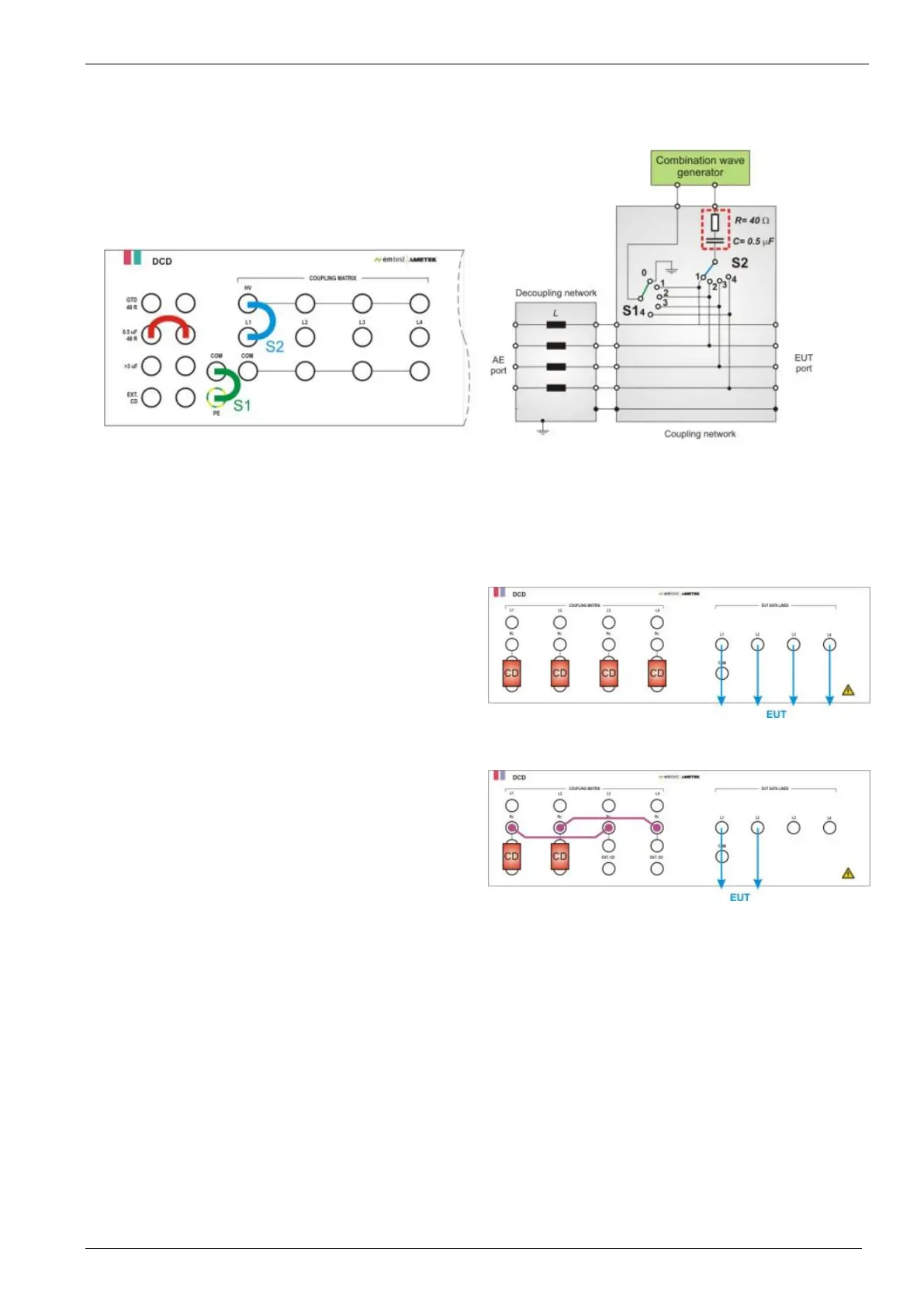
9.7. Coupling network DCD st, 4 lines
Each of the 4 lines has an impedance of= 160 Ω
All four lines are connected by using a coupling device (CD)
Figure 49 - 4 Data Line Setup
Two lines are switched in parallel. Each of the 2 lines has an
impedance of= 80Ω (160 Ω // 160 Ω)
L1 = (L1’ // L3’)
L2 = (L2’ // L4’)
Figure 50 - 2 Data Line Setup
- Line 1 and Line 2 coupeld with a coupling device (CD) to the EUT output.
- Lines L1 is parallel with L3
- Lines L2 is parallel with L4
 Loading...
