AMETEK CTS Quick start guide - Conducted
1.00 35 / 50
8.5. Front view (model-specific distinctions)
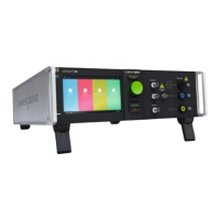
Figure 40 - coupling NX front side (model for 16 A / 32 A)
1 Active LED
2 Phenomenon (Burst, Ring Wave, Surge)
3 Coupling indication LED
4 Test Supply AC, DC and Over temperature
5 "TEST ON” button
6 EFT input from compact NX generator
7 EFT output to capacitive coupling clamp
8 EUT Output L1/DC+, L2, L3, N/DC-, PE
9 GND reference for EFT verification
10 Output HV & COM to external Surge CDN
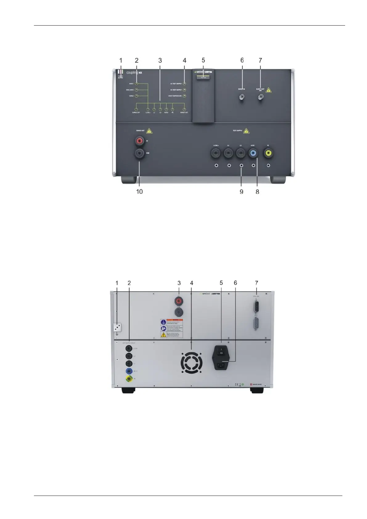
8.6. Rear view (model-specific distinctions)
Figure 41 - Rear side coupling NX
1 Reference earth connection (Screw M4)
2 EUT power L1 & dc+, L2, L3, N & dc-, PE
3 Input HV & COM from NX generator
4 Ventilator
5 Power switch
6 Mains connector and fuse (5 x 20 mm)
7 Sys Link