AMETEK CTS Quick start guide - Conducted
1.00 38 / 50
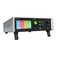
Figure 44 - AE Protection
9.2. AE Protection for auxiliary equipment
Depends on the application different
protection units are awailable to protect
the auxiliary equipment.
The protection unit is changeable to get
the best protection for the auxiliary
equipment
9.3. Device functions and operating
The difference between the various models is:
- Number of data lines (DCD sr 4-x series with 4 lines, DCD sr 8-x series with 8 lines)
- nominal voltage and current level of the signal- and data lines
- various test voltage level of 5 kV and 7 kV
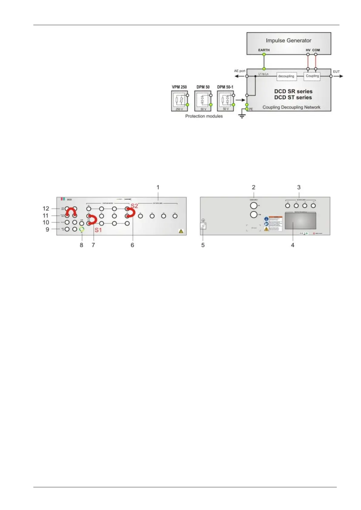
9.4. Coupling network DCD sr
Figure 45 - DCD Connections
2 HV COM input (Generator)
3 Signal input (AE port)
4 Protection device
5 PE earth plug to ground
6 Coupling HV to L1 - L4 (S2)
7 Coupling L1 L4 to COM (S1)
8 Connection COM-GND (S1)
9 External coupling
10 Coupling 3 µF Ringwave
11 Coupling 0.5 µF / 40 Ω Surge
12 Coupling GDT (inside the bridge) / 40 Ω Surge