PARSTAT MC Hardware Manual
PARSTAT MC Hardware Manual 12
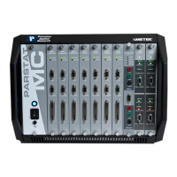
3. PARSTAT MC (PMC) INSTALLATION
This chapter describes the PARSTAT MC connectors and indicators and shows you how to connect it to
the host PC, electrochemical cell, and other equipment you might wish to use with it. The pinouts for
Auxiliary and Analog Connector and cell cable connector are listed in Sections 6.
3.1. Enabling the USB port on your PC
Some PC manufacturers ship their PCs with the USB port disabled. Check for this before trying to use the
PARSTAT MC. If the port is disabled, follow the manufacturer’s instructions for enabling it.
3.2. High Data Acquisition Rates and Number of Channels
The VersaStudio control software can run up to 32 channels of potentiostats from a single computer. High
channel counts especially in combination with high data acquisition rates can burden the system with the
requirement for high-speed data transfer.
There are three possible rate-limiting parameters that should be considered if operating this configuration:
data from the potentiostat (USB performance), data at the PC (Processor speed), and data to the hard drive
(Time to Write for the Hard Drive).
3.2.1. USB performance
VersaStudio and the PARSTAT MC are compatible with both USB 1.1 and USB 2.0. USB 2.0 is
recommended for faster data transfer rate requirements.
3.2.2. Processor speed
The processor of the computer itself is another possible bottleneck to fast data transfer
While minimum specifications are published, the fastest processor possible will help ensure that this does
not limit the performance of the system at high-speed data transfer.
3.2.3. Read/Write speed of the hard drive
There is a certain amount of time required to both read and write from/to the hard drive. Minimizing this
time helps to make sure it is not a bottleneck. Currently solid-state drives are the fastest write/read
technology in the market. However, large sizes may be difficult to source. The faster the Read/Write time,
the better.
The consequence of data acquisition rate of the total number of channels exceeding the capability of the
system to process the data is latency in the display of the data on the computer.
There is a 4 million data point buffer per potentiostat channel. Data collection is not affected by latency in
display. The experiment continues to run and data files and display are populated as data transfer happens.
However, if the 4 million data point buffer per channel goes into an overrun condition, data outside of its
buffer will be lost.