PARSTAT MC Hardware Manual
PARSTAT MC Hardware Manual 6
Three 16-bit analog-to-digital converters (ADCs) to measure current (I), potential (E), SYNC ADC INPUT.
An onboard microprocessor to perform the experiment defined by the operating software.
Onboard memory to store the programmed parameters and data point values.
Each PMC-1000 operates with VersaStudio in either the potentiostatic or galvanostatic mode, described
below.
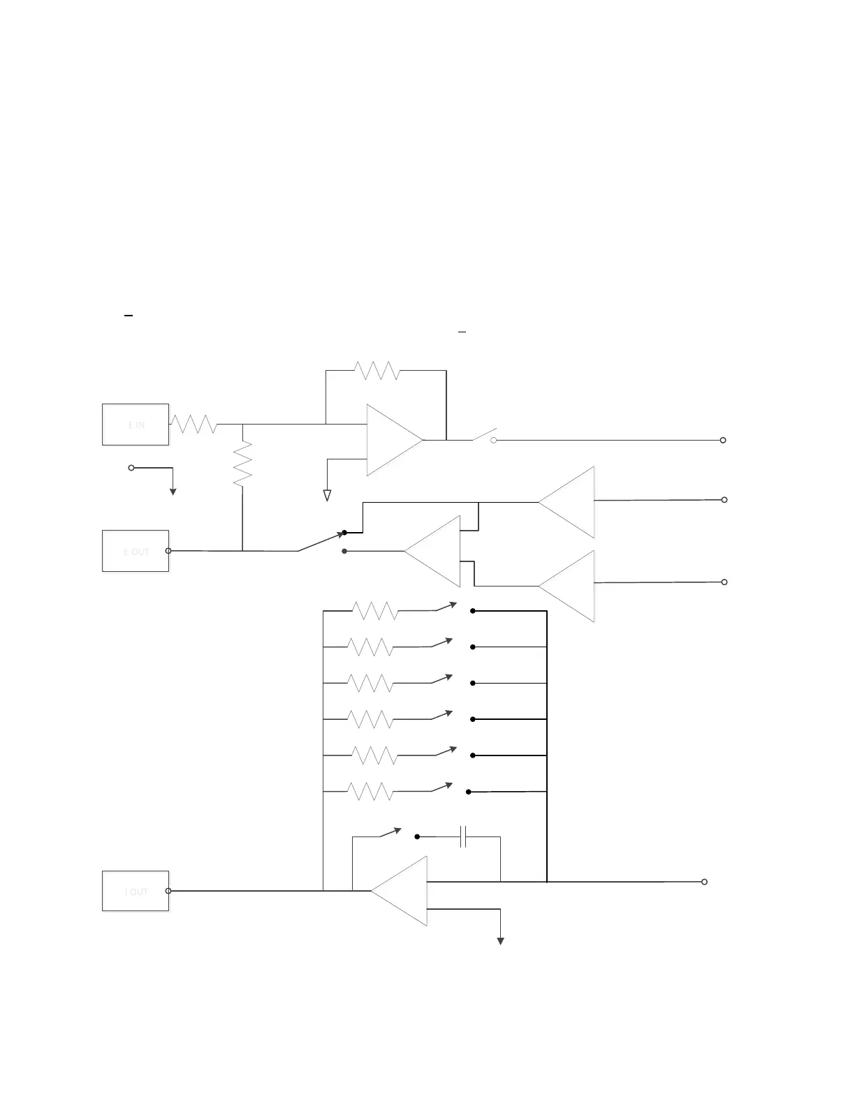
1.2.1. Potentiostatic mode
In this mode, the PMC-1000 controls the potential at the working-sense electrode with respect to the
reference electrode (see Figure 2). The counter electrode is driven to the potential required (consistent with
the + 12 V compliance of the control amplifier) to establish the desired working potential. The range over
which the working electrode potential can be controlled is + 10 V.
-
+
WORKING
I OUT
I OUT
I/E CONVERTER
CURRENT RANGES (EXAMPLE)
2 mA
200 uA
20 uA
2 uA
200 nA
20 nA
E IN
E IN
-
+
POWER AMP
Cell Switch
COUNTER
SINGLE ENDED
-
+
REFERENCE
SENSE
E OUT
E OUT
DIFFERENTIAL
ELECTROMETER
Figure 2. Potentiostat-Mode Block Diagram