PARSTAT MC Hardware Manual
PARSTAT MC Hardware Manual 23
4.1.3. The Potentiostat Module (PMC-1000)
A potentiostat channel may be installed in any chassis slot except the dedicated power supply slot. Up to
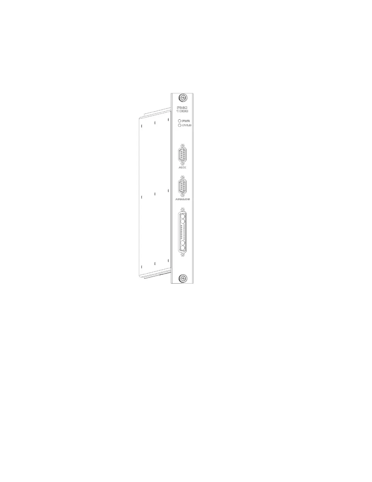
eight potentiostat channels may be installed at one time. The PMC-1000 module is shown here.
Figure 14. The PMC-1000 Potentiostat Channel
The front panel of the PMC-1000 has the cell cable connector, an analog connector, an auxiliary connector,
and two LED indicators. When the PWR LED is lit, the channel is receiving power. When the OVLD LED
is lit, an overload condition exists on that channel.
The PCB for the module extends outside of the case at the top and bottom of the module. These PCB
edges help to locate the module in the chassis, aligning and retaining it properly. The thumbscrews fasten
the module to the front of the chassis.