PARSTAT MC Hardware Manual
PARSTAT MC Hardware Manual 57
5.4. AUXILIARY INTERFACE Pinouts
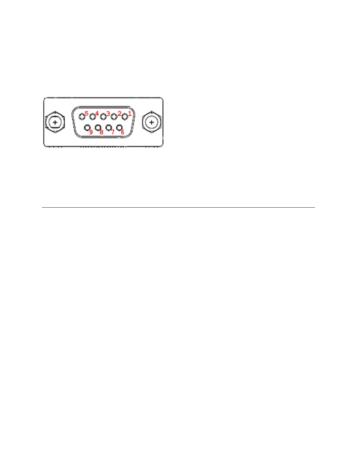
5.4.1. Pin Numbers for PMC Auxiliary connection and Analog Connection.
Figure 47. Labeling of Pins on DB9 connections for PMC AUX01 and PMC ALG01
5.4.2. Pins Outs for PMC AUX01 Cable
Table 1. PMC AUX01 Cable PinOuts
Using the VersaStudio software, an experiment can be held, waiting on this
TTL trigger input signal to be read.
When using the PMC-1000 with a Model 303 or 303A Static Mercury Drop
Electrode (SMDE) via a Model 507 interface,
this signal causes the electrode to perform a DISLODGE/DISPENSE
operation on command from the host PC.
A TTL trigger output is provided on this line with the VersaStudio software
When using a Model 303 or 303A SMDE via a Model 507 Interface, this
signal controls the electrode’s PURGE function in response to commands
from the host PC .
This signal controls the Model 303 or 303A’s STIR function in response to
commands from an external computer. It is assumed that the electrode is
being used with a Model 305 stirrer.