PARSTAT MC Hardware Manual
PARSTAT MC Hardware Manual 7
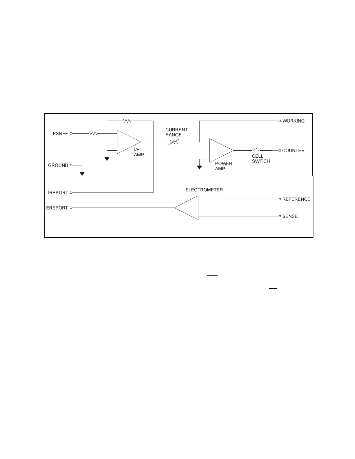
1.2.2. Galvanostatic mode
In galvanostatic operation, the PMC-1000 controls the current between the counter and working electrodes
at the specified fraction of the selected current range (up to the maximum of the current range; see Figure
3). The counter electrode is driven to the potential required (consistent with the + 12 V compliance of the
control amplifier) to establish the desired cell current. The reference electrode is not used in the control
loop, but is usually used to measure the potential at some point in the electrochemical cell relative to the
working-sense connection point.
Figure 3. Galvanostat-Mode Block Diagram
1.3. Software
The PMC-1000 is fully compatible with the VersaStudio software only. The PMC-1000 will not operate with
any other software other than that specified in this manual or the most recent documentation available on
the web site (http://www.princetonappliedresearch.com). Likewise, the PMC-1000 does not have an open
command set to allow user programming outside of the VersaStudio software. The software is designed
specifically to work with Windows 7, Windows 8 and Windows XP. It is highly recommended that either
Windows 7 or XP be used.
1.4. Polarity Convention
The PMC-1000 hardware follows the American polarity convention. (Positive current is cathodic; that is, a
current is defined as positive if reduction is taking place at the working electrode. Negative current is
anodic; that is, a current is defined as negative if oxidation is taking place at the working electrode. If the
working electrode is driven positive with respect to the equilibrium potential, the resulting current is anodic.
If the electrode is driven negative with respect to the equilibrium potential, the resulting current is cathodic.)
1.5. Inspecting Your New Instrument