Using Series 2000 RCU Signals | D-1
USING SERIES 2000 RCU SIGNALS
You can use Series 2000 control unit signals to control your own switching
valve to switch from the sample to calibration gases. Note, however, that
we recommend that you use the Factory-Provided Remote Calibration
Unit (RCU) as the best way to control the calibration process.
You must have and auto calibration card installed in your Series 2000
controller to be able to use these signals.
RCU signals allow you to control the valves you use to switch between
the process gas and the calibration gases. See the Controller/User Interface
chapter for help on how to set up the calibration process from software.
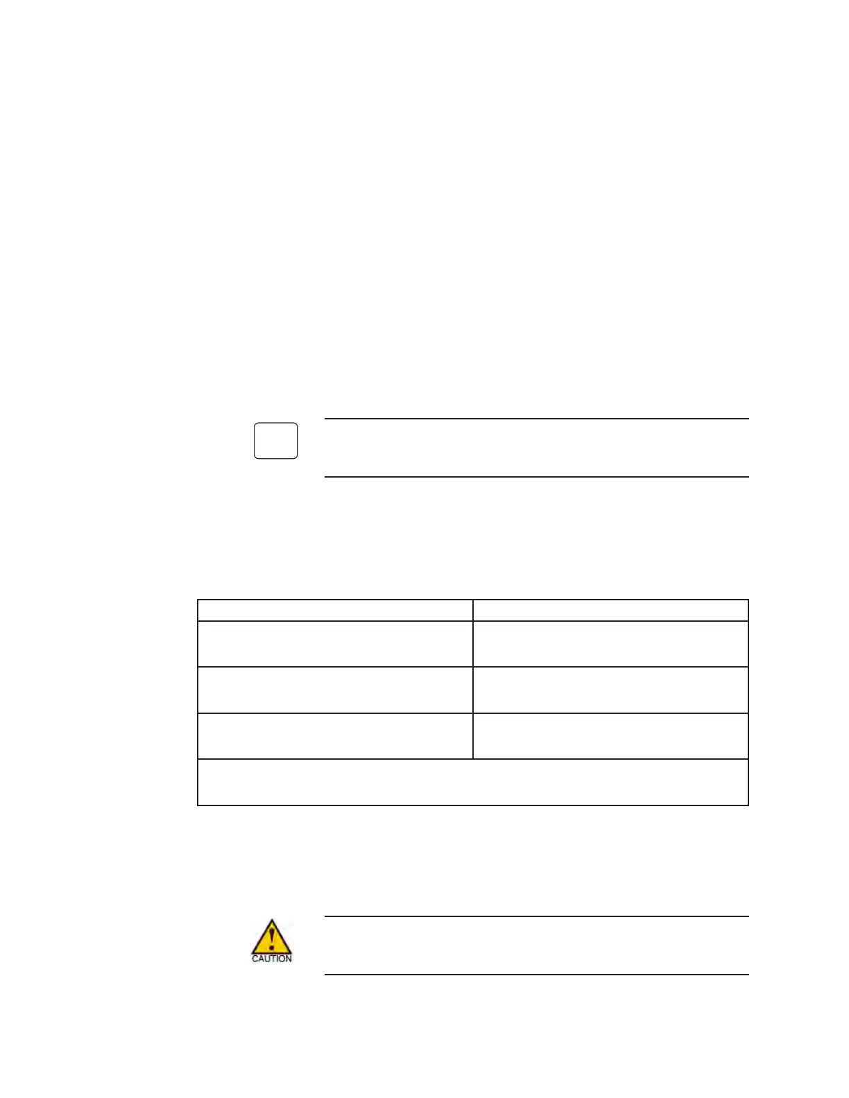
Figure D-1.
Control unit signals
to initiate a remote
calibration.
If measuring PPM gases, use a packless valve to switch between the
sample gas and the calibration gas.
Control Signals *High or Low Signal from Control Unit
Calibration Control Signal
(labeled Aspirator on control unit)
System Not in Cal. - Low
System Calibration - High
Zero (Low) Cal Gas
(labeled Zero on control unit)
Calibrating Zero Gas - High
All other Times - Low
Span (High) Cal Gas
(labeled Span on control unit)
Calibrating Span Gas - High
All other times - Low
*High signal is 15 volts (sources current), low signal is 0 volts (no current sourced).
Maximum source curent - 250 mA.

 Loading...