3-24 | Thermox TM 2000 Oxygen Analyzer
Current Output Connections
Current output connections are labeled as follows on the wiring card of
the Series 2000 control unit (see Figure 3-22):
IOUT1 + and -
IOUT2 + and -
These current outputs are referenced as current outputs 1 and 2 in soft-
ware (see the Analog Range Key Chapter for help on defining current
output settings in software). Be sure to observe polarity when connecting
current output devices to these terminals.
Current outputs 1 and 2 are capable of driving up to 1200-ohm loads.
The standard control unit with no options provides two current outputs.
These two current outputs (1 and 2) are isolated from the control unit, but
are not isolated from each other.
If you intend to power current outputs from an external power sup-
ply, see the “Current Outputs: Other Applications” appendix.
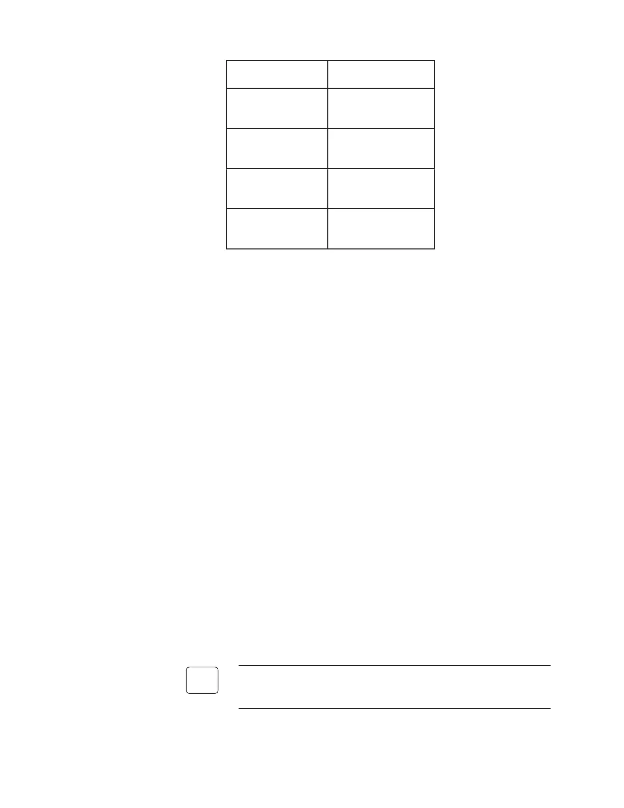
CONTROL UNIT
LABEL
SENSOR TERMINAL
NUMBER
Cell +
Cell -
1
(one pair)
2
Furnace
15V COM
3
(one pair)
4
T/C +
T/C -
5
(one pair)
6
15V SPLY
15V SPLY
12
(one pair)
12
Figure 3-21.
Standard sensor
connections.
 Loading...