Installation and Start-Up | 3-23
Sensor AC mains supply connections
Connections for AC mains supply to the sensor are labeled as follows:
L Line Connection
L2 Neutral (USA)
Chassis Stud Equipment Ground (Protective Conductor)
There is no power switch or circuit breaker on the sensor. It must be pro-
tected by installing it on a circuit-protected line, maximum 15 amperes,
with a switch or circuit breaker in close proximity to the sensor and within
easy reach of an operator. Mark the switch or circuit breaker as the sensor
disconnecting device.
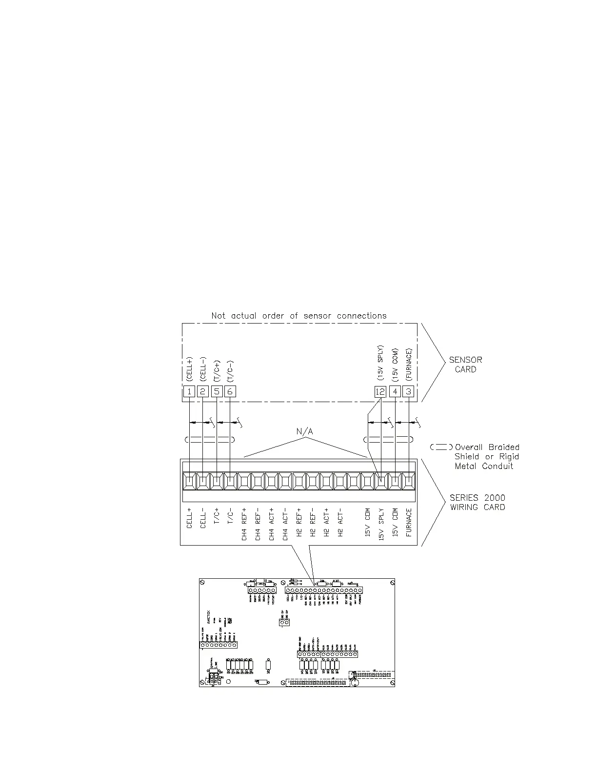
Standard sensor connections
Make the following connections from the control unit to the sensor using
twisted pair cable (see Figure 3-20 and Figure 3-21):
Figure 3-20.
Sensor connections.
 Loading...