10
3.1.2 PCB Removal / Replacement
If the PCB’s have to be removed the following precauons should be observed;
1. Removing the door will provide beer access to the boards and ensure the hinges are not
accidentally stressed.
2. Personal an- stac procedures must be followed.
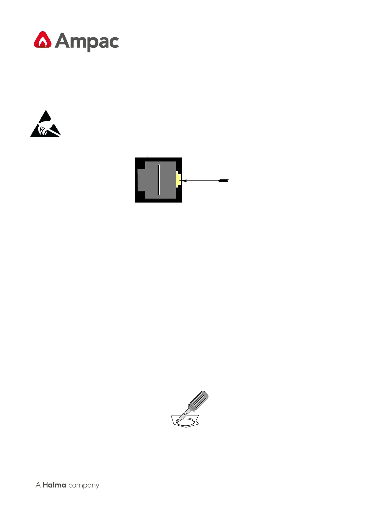
3. When disconnecng the telecom style (RJ45) connecng cable from the PCB, make sure that
the cable remains connected to at least one board to prevent it being misplaced.
Figure 8: RJ45 Connector
Note: Care should be taken when detaching this connector as it is necessary to depress the small
locking tab to unlock the connector from its base. To reconnect the cable the connector must rst be
correctly aligned then pushed into the socket so it locks into posion.
1. Carefully remove the retaining screws at each corner of the board taking care not to damage
any of the components.
2. Place each board into an- stac storage once removed.
3.1.3 Removing the Knockouts
Carefully decide how the wiring will be brought into the panel then remove the required knock-outs
for the bushes and cables.
The knock-outs should be removed with a sharp tap in the rim of the knock-out using a at broad-
bladed screwdriver. Use of excessive force could damage the enclosure around the knock-out.
Always ensure if a knock-out is removed, the hole is lled with a good quality cable gland. Any unused
knock-outs must be securely blanked o.