17
6.3 TB3 Inputs
Common Terminal TB3
Used with the inputs 0v potenal.
Spare Input TB3 /1
Not used (Monitored input defaults to general alarm as explained below).
Class Change Input TB3 / 2
Input is provided to allow a remote connecon to operate the sounder alarm outputs. The input is
acve when it is pulled down to 0v potenal. When acve the sounder alarms output will operate
connuously, no indicaon shall be given and no other output will operate. This input is monitored,
(monitoring may be disabled) and is non-latching.
Alert Input TB3 / 3
Input is provided to allow a remote connecon to operate the sounder alarm outputs. The input is
acve when it is pulled down to 0v potenal. When acve the sounder alarm outputs will pulse at a
rate of 1sec on 1 sec o, no indicaon shall be given, no other output will operate. This input is non-
latching
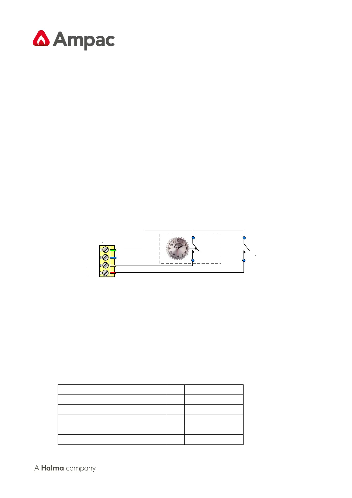
Figure 15: Auxiliary Input Wiring
6.4 Zones
6.4.1 Detector Interface
All zones will be programmed to operate in one of the 6 dierent conguraon modes each with a
reset me in the order of > 1 second < 2 seconds. To maintain “back up “mes a maximum of thirty
two (40) 24V re detectors can be connected to each 24mA current limited zone interface.
6.4.2 Detector Conguration
The operang conguraon modes are, LCD abbreviaons shown are;