19
6.7 Conventional Sounder Circuit Wiring
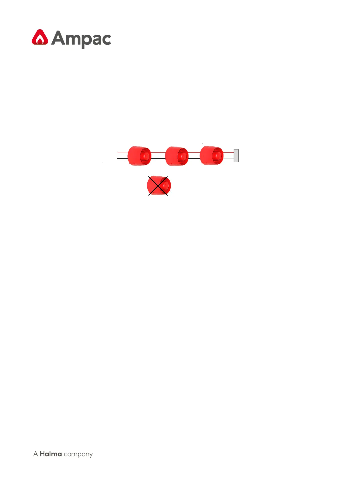
The four alarm outputs can be used for convenonal sounder circuits.
Note: All Sounders must be polarised.
An end of line resistor (10k) must be connected at the end of each circuit to allow the wiring to be
monitored.
The wiring for each circuit is connected to the relevant 5mm connector block on the Main Control
PCB and the screens terminated to the chassis earth terminal.
Figure 17: Typical Sounder Circuit Wiring
6.7.1 Sounder Loading and Distribution
The FACP's Power Supply is designed to give a maximum output current of 2A. In addion to powering
the sounders, this current is also used for handling short circuit faults, supplying the Panel's baery
charging circuit and any output relays that may be ed. As a safe margin and to allow for these other
loads, the total sounder loading for the panel should not exceed a maximum of 1.5A.
Each Output and or Sounder circuit is current limited to a maximum alarm current of 500mA. The
Sounders should be distributed throughout the building according to the sound levels required, and
the load distributed as equally as possible across each circuit.
6.8 Outputs –Monitored Modied Open Collector TB5
Denion: A monitored modied open collector output for user connecons such as a relay.
Via the front panel it is possible to program which zones will operate any of the outputs.
6.8.1 Alarm Output TB5 1/2
The output operates in parallel to the Alarm Output relay and energises in the alarm condion of a
zone that is isolated.
The output is current limited to 25mA @ 27VDC.
If a zone is congured as non-latching it will not operate this output.
6.8.2 Fault Output TB5 3/4
The output operates in parallel to the Fault Output relay and de-energises in any fault condion.
The output is current limited to 25mA @ 27VDC.
All faults except “System Faults” are non-latching.