16
6 Wiring to the Main Card BRD25MCB
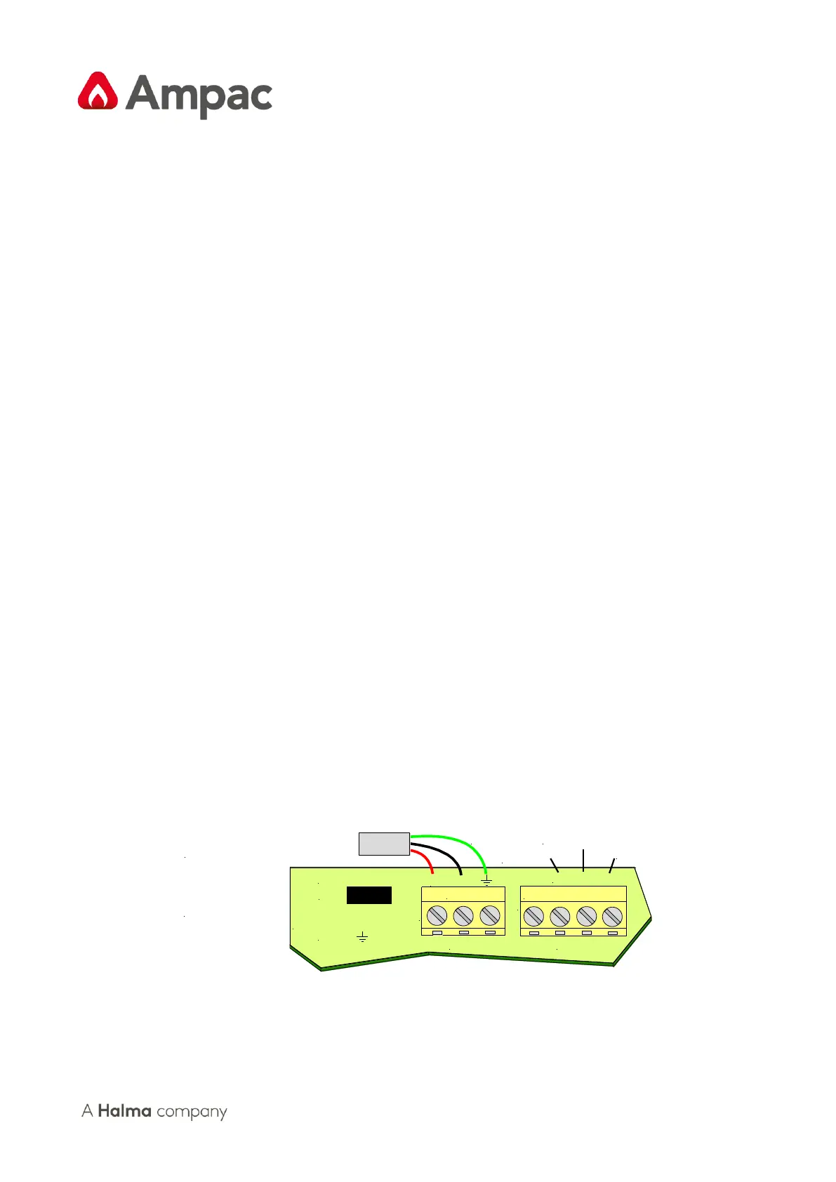
6.1 Earth Monitoring
The earth monitoring disable/enable feature is accessible via the SYSTEM menu at access level 3.
Disabling the earth monitoring does not illuminate the Earth Fault LED on the control panel.
Note: If ZoneSense PLUS is connected to a third party system which has earth monitoring and its
earth monitoring is being aected by ZoneSense PLUS even aer being disabled through
programming the resistor R22 on the Main Card in ZoneSense PLUS can be removed.
6.2 Communications
External Communicaons Terminals (RS485) TB2 1, 2 & 3
The RS 485 output drives the remote cards and mimics up to a distance of 1.2km from the panel itself.
The external cabling (2x2 shielded pair plus power) is wired to TB2 +, - and earth.
Note: If a fault occurs on the communicaons bus the common FAULT and SYSTEM FAULT LED’S
are illuminated and the details can be displayed on the LCD by selecng the Faults Menu.
Remote Cards
The number of cards that can be installed on the external communicaons bus are:
➢ 8 x Remote Zone Mimic Indicator Cards
➢ 1 x Remote Relay Board. provides 8 sets of normally open (NO), normally closed (NC) and
Common (C) voltage free contacts rated at 1A @ 30VDC.
Main Card Comms Link K1
LK1 MUST be inserted when only the front door panel cards and the Main Card are used as an FACP.
If this is not the case and TB2 is cabled to LED Repeaters and / or 8 Way Remote Relay Boards a link
is inserted in the last board to complete the communicaon circuit or if boards are mounted on the
back pan and communicaons are wired from the Main Card then the last board in this chain MUST
be terminated.