23
7.2 Installation and Cabling of Add On Cards & Boards
CAB1925 to Batteries
CAB1902
CAB1905
CAB1911 TO MAINS EARTH
CN1CN2 CN2 CN1
ALARM 2
N/CCOM
N/0
BATT FAIL
N/CCOMN/0
ISOLATE
N/CCOMN/0
FAULT
N/CCOMN/0
ALARM 1
N/C
COM
N/0
TB1-TB5
POWER
0V +27V
0V +27V
CN2 CN1
CN3
CN4
POWER
+27V
0V
CN1
CN2
+27v Power fitted when Relay or Termination Boards are fitted
CN1
CN2
CN5
CN9
CN1CN2
CN2
CN1
CAB2200 CAB2117
CAB1905
CAB2200
CN6
POWER
+27V
0V
CN1
CN2
POWER
+27V
0V
CN1
CN2
MAIN CONTROL CARD
OPTIONAL CARDS
AGENT RELEASE
FAN CONTROL
GENERAL INDICATOR
OPTIONAL BOARDS
AGENT TERMINATION
RELAY
FAN TERMINATION
INPUT
SOUNDER TERMINATION
A BATT BOX IS REQ
IF THESE BRDS ARE FITTED
OTIONAL
BRIGADE BOARD
CAB2200
CAB2200
BRD25ARB PCB0783 (AGENT RELEASE MODULE)
BRD25ATB PCB0787 (AGENT TERMINATION BOARD)
BRD25BBA PCB0779 (BRIGADE BOARD)
BRD25EWRB PCB0770 (8 WAY RELAY BOARD)
BRD25FCB PCB0783 (FIRE FAN MODULE )
BRD25FTB PCB0780 (FAN TERMINATION BOARD)
PSU1887
CN3
CN4
CN3 CN4
CN3
CN4
BRD25GIB PCB0781 (GENERAL INDICATOR CARD)
BRD25MCB PCB0769 (MAIN CONTROL CARD)
BRD25PSU PCB0813 (POWER SUPPLY UNIT)
BRD25SIPB PCB0778 (SINGLE INPUT BOARD)
BRD25SOPB PCB0772 (SOUNDER OUTPUT BOARD)
OPTIONAL CARDS
AGENT RELEASE
FAN CONTROL
GENERAL INDICATOR
OPTIONAL BOARDS
AGENT TERMINATION
RELAY
FAN TERMINATION
INPUT
SOUNDER TERMINATION
A BATT BOX IS REQ
IF THESE BRDS ARE FITTED
OPTIONAL BOARDS
AGENT TERMINATION
RELAY
FAN TERMINATION
INPUT
SOUNDER TERMINATION
A BATT BOX IS REQ
IF THESE BRDS ARE FITTED
BUS 1
BUS 2
BUS 3
BOARD
IDENTIFIERS:
CN8
CN10
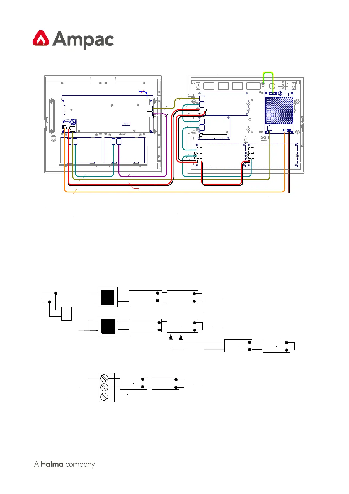
Figure 18: Typical Wiring, Ancillary Card and Board Posioning Within the ABS FACP
7.3 Terminating the Communications Bus
TB2
K1
Shield
CN5
CN9
Front Panel
Card 1
Front Panel
Card 2
Backpan
BRD 1
Backpan
BRD 2
INSERT
LK1
Remote
Card 1
Remote
Card 2
LCS 1
LCS 2
INSERT
LK1
INSERT
LK1
INSERT
LK1
If Agent Release is fitted to the FACP there will be an Agent Termination Board mounted on the Backpan.
Local Control Stations can then be fitted at some location remote from the FACP. These LCS's communicate
with the ATB via a second RS485 bus hence the last LCS in the chain will have to be terminated
Note: If Backpan boards AND remote facilities
are fitted the front panel cards are not terminated
To
TB1 Agent Termination Board
Fit K1 if only the
Main Control
Card is used as
the FACP or
1 Bus is used.
SEE TABLE
BELOW
RS485
+
-
BUS 1 ( B1 )
BUS 2 ( B2 )
BUS 3 ( B 3)
( Link 1 in Table below )
( Link 2 in Table below )
( Link 3 in Table below )
BUS 4 ( B 4)
Fit LK1 to last LCS
Figure 19: RS485 Communicaon Bus Terminang