18
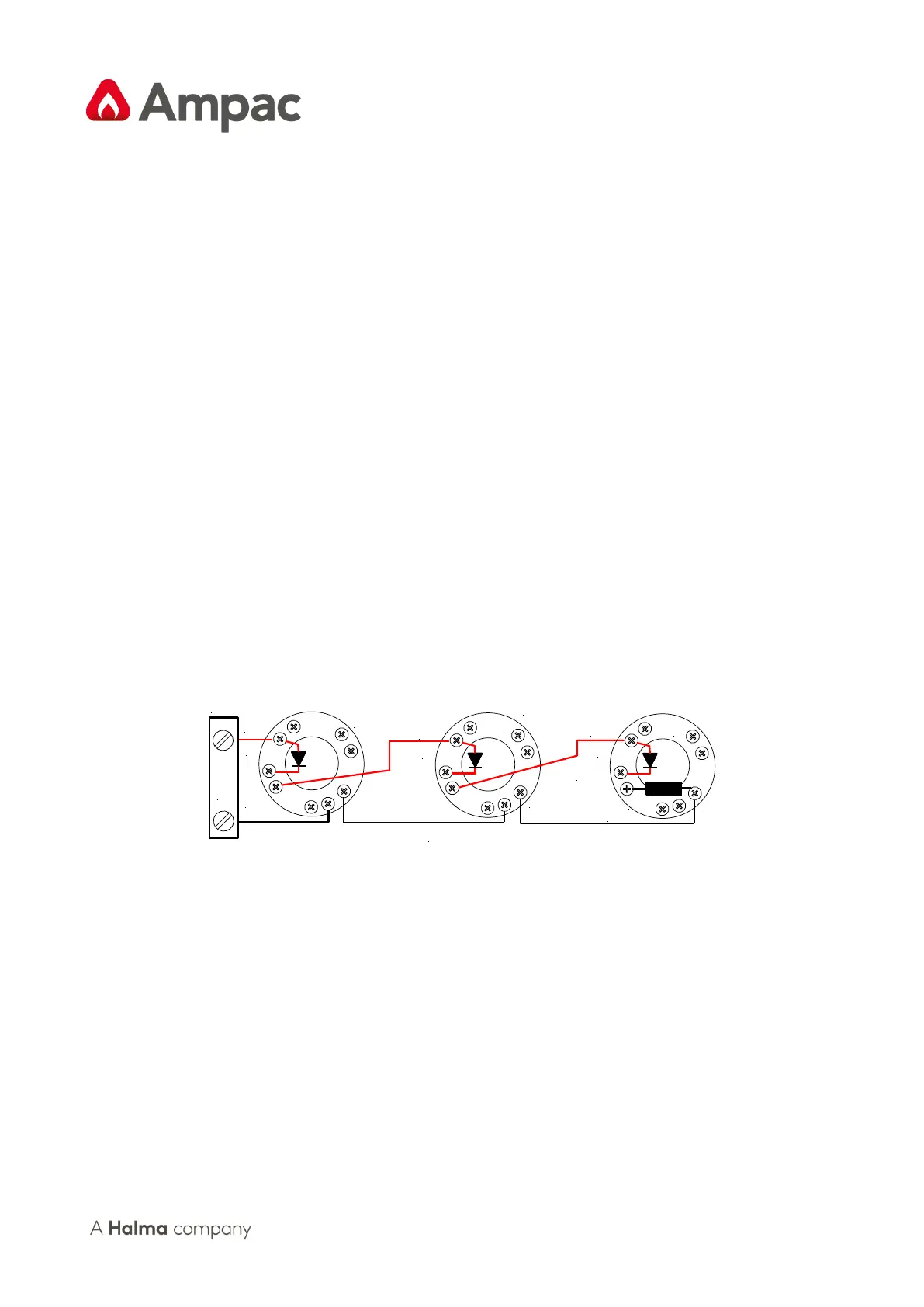
6.4.3 Detector Removal Facility
This facility allows for up to 20 detectors to be removed from their bases at any one me. If a detector
head is removed a fault will be indicated on that zone and all the other devices retain the ability to
iniate an alarm. This facility requires;
➢ Schoky diodes having a voltage drop of 0.2 – 0.3 of a volt to be installed across L1 in and L1
out on the detector base. The limitaon on the number of heads that can be removed is a
direct result of the cumulave eect of the voltage drop across each diode. Diodes will not
be required if the head removal facility is not required.
➢ The use and programming of a bipolar capacitor as the end of line (EOL) device.
6.5 Zone Circuit Wiring TB13 - 14
Zone circuit connecons are made directly to TB13 & TB14 on the Main Card and if screened cabling
is used the screen is terminated at the panel's chassis earth terminal.
Reminder 1: A maximum of 32 ZoneSense PLUS compable Opcal / Heat Detectors or Manual
Call Points can be ed to each circuit and mixed in any order.
Reminder 2: An End of Line Capacitor must be connected across the terminals of the last device
on each circuit. Unused Zones must have an End of Line capacitor ed at the panel.
Figure 16: Typical Detector Wiring with Detector Removal Facility Diodes
6.6 Monitored Alarms Outputs
The panel has 4 dedicated individually monitored outputs terminated to TB4 which are;
➢ Rated at 500mA @ 24VDC nominal;
➢ Protected against short circuits;
➢ Monitored for open and short circuit condions even when an output is acve. The
monitoring operates on a reverse voltage principal and will indicate a fault within 60 seconds.
➢ Programming which zones will operate any of the outputs is done via the front Panel.