14
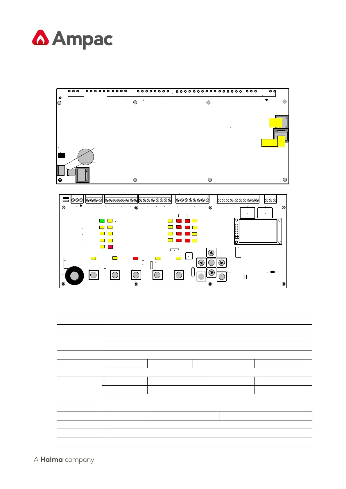
5 Main Control Card BRD25MCB –A (4 Zone) B (8 Zone)
The Main Control Card and its front display panel combined with the Power Supply / Baery Charger
/ baeries form the basis for the ZoneSense PLUS FACP.
CN5: Comms To
Internal Boards
CN9: To Any Cards
Fitted To The Front Panel
Keyswitch
Link
CN1
CN8
CN10
TP61
TP60
TP59
TP58
TP40
TP39
TP37
TP36
TP35
TP34 TP33
TP32
TP31
TP30
TP29
TP28
TP27
TP26
TP25TP24
TP23
TP22
TP21 TP20
TP19
TP18 TP17
TP1
TP2
TP3TP4
TP5
TP6
TP7
TP8
TP9
TP10
TP11
TP12
TP13
TP14
TP15
TP16
MON.
+ -
+Z3-
+Z5-
+Z1-
+Z6-
+Z8-
-
+Z7-
1 C
OUTPUTS
3
+Z2-
+Z4-
+3-
+4-
2
+
+1-
+2-
+ -
REV._1
ZONES
+- +- - + - +
EARTH
DISABLE
INPUTS
COMMS
BOTTOM OVERLAY
CN1: The Link is inserted when the
Front Panel Keyswitch is not used
CN8: 27V From the Power Supply
CN10: 27V to the Internal Modules
CN6: Monitoring Comms from the Power Supply
TP 1 to 44
( See the Terminal Block
Quick Reference for Detail )
Cutout
///
NO NC
C
///
NO NC
C
FUSE:5A.
OUTPUTS
NO C NC
MON.
COMMS
24VDC
INPUTS
ZONES
OUTPUTS
K1
U12
TB14
TB13
Q20
SW12
SW11
SW10
SW9
SW8
SW7
SW6
SW5
SW4
SW3SW2
SW1
R22
CN2
D2
D3
D4 D5
D6 D7
D8
D9
D10
D11
D12
D13
D14
D15
D16
D17
D18
D19
D20 D21
D22
D23
D24
D25
D26
D27
D28
D29
D31
D37
D38
TB2
TB3
TB4
CN7
TB12
TB5
BZ1
FS1
RL2
RL3
U2
U3
U4
U6
U18
U19
U1
X1
COMMS
INPUTS
DISABLE
EARTH
ZONES
REV._1
+ A -
+2-
+1-
+
+4-
+3-
+Z4-
+Z2-
OUTPUTS
+Z7-
-
+Z8-
+Z6-
+Z1-
+Z5-
+Z3-
+ F -
MON.
TOP OVERLAY
ALARMS 1 - 4
FIRE FLT
NO C NC
FLTANC
+ -
RST
LCD
+
Menu
Enter
Evacuate
Reset
Silence
Buzzer
Silence
Resound
Override
Power
Power Fault
System Fault
Earth Fault
COM SP C/C ALT
Alarms Status
Ancillary Output Disabled
Alarms / Fault Disabled
Test
Fault Output Fault Disabled
Fire Output On
Fire
Fault / Disabled / Test
Delay
Alarms
Fire
Fault
Disabled
Cancel
Figure 12: Main Control Card Top and Boom Layout
Cabling
Link pins 1 & 2 when the front panel keyswitch is NOT used.
Comms and +/- 27VDC to the front panel cards.
Monitoring / Comms from the Power Supply.
+/- 27VDC and earth from the Power Supply / Charger.
Comms to the internal back plane boards.
Pin connecons are the same as CN5
1 +27VDC and 2 0V to the internal back plane boards