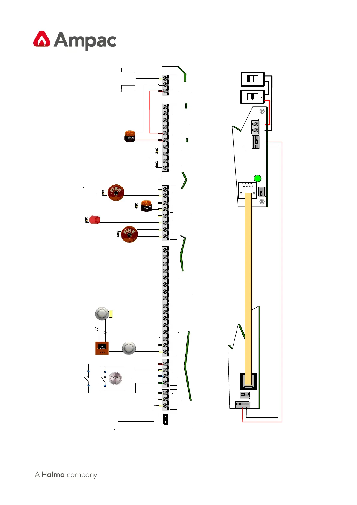
EOL
Capacitor
Maximum of 32
Devices per Zone
ALL Un-used Zones MUST be Terminated in an EOL
Comms
Link
3 Sec
Reset
Pulse
Note: Comms Link
is required when
only one Systems
Comms board is used
EOL
Resistor
EOL
Resistor
EOL
Resistor
EOL Termination Values
Zone = 10uf,3K3, 4K7,
6K8 or 10Kohms
Monitored O/P's = 10Kohms
CN8:27V In from CN4 of the P/S
CN10: 27V Out to Internal Cards & Boards
CN6 PSU Control from CN2 of the P/S
Open Collector O/Ps Current Limited to
25mA. and Detector Removal Facility Available
4 X Monitored
Alarms Outputs
Maximium
500mA / 24V
Monitored
Current Limited
25mA O/P's
Voltage Free
Contacts 1A/30V
Monitored
24V 500mA
O/P
+24v / 100mA
0v
Power Supply Unit ( BRD25PSUA )
Rear of Main Board
Front of Main Board Illustrated External Cabling
Power Supply Main Board Internal Wiring
TB2
TB3
TB13
TB4
TB5
TB12