Page 48
20 EN54 ABS Inner Front Panel Conguration Labelling
ZONE
1
CONFIGURATION
NORM / AVF / NON / SELF / AT1 / AT2
BELL
WARN
ACF
ASE
ALARM
B ALARM 2
RELAY 1 RELAY 2 RELAY 3 RELAY 4 RELAY 5 RELAY 6 RELAY 7 RELAY 8
NORM / AVF / NON / SELF / AT1 / AT2
2
NORM / AVF / NON / SELF / AT1 / AT2
3
NORM / AVF / NON / SELF / AT1 / AT2
4
NORM / AVF / NON / SELF / AT1 / AT2
5
NORM / AVF / NON / SELF / AT1 / AT2
6
NORM / AVF / NON / SELF / AT1 / AT2
7
NORM / AVF / NON / SELF / AT1 / AT2
8
SWITCH
INPUT
ACF ISOL
RESET
LATCHING
FUNCTION
INHIBIT ZONES
LATCHING
ACF ISOLATE
FAN 1 FAN 2 FAN 3 FAN 4
A / F / I
A / F / I
A / F / I
A / F / I
A / F / I
A / F / I
A / F / I
A / F / I
A / F / I
A / F / I
A / F / I
A / F / I
A / F / I
A / F / I
A / F / I
A / F / I
A / F / I
A / F / I
A / F / I
A / F / I
A / F / I
A / F / I
A / F / I
A / F / I
A / F / I
A / F / I
A / F / I
A / F / I
A / F / I
A / F / I
A / F / I
A / F / I
A / F / I
A / F / I
A / F / I
A / F / I
A / F / I
A / F / I
A / F / I
A / F / I
A / F / I
A / F / I
A / F / I
A / F / I
A / F / I
A / F / I
A / F / I
A / F / I
A / F / I
A / F / I
A / F / I
A / F / I
A / F / I
A / F / I
A / F / I
A / F / I
A / F / I
A / F / I
A / F / I
A / F / I
A / F / I
A / F / I
A / F / I
A / F / I
Y / N
Y / N
Y / N Y / N
Y / N
Y / N
Y / N
Y / N
Y / N
Y / N
Y / N
Y / N
Y / N
Y / N
Y / N
Y / N
Y / N
Y / N
Y / N
Y / N
Y / N
Y / N
Y / N
Y / N Y / N
Y / N
3 / 4 / 5 3 / 4 / 5
Y / N
Y / N
3 / 4 / 5
Y / N
Y / N
3 / 4 / 5
Y / N
Y / N
B ALARM 1
AGENT RELEASE
AUTO DELAY - SECS
MANUAL DELAY - SECS
PRESSURE SWITCH
No OF LCP'S
SOLENOID / PYROGEN / METRON
0 / 15 / 30 / 60 /
NO / NC / NA
1 / 2 / 3 / 4
0 / 15 / 30 / 60 /
SYS
SOUNDER
1
SOUNDER
2
SOUNDER
3
SOUNDER
4
SOUNDER
5
SOUNDER
6
SOUNDER
7
SOUNDER
8
EOL VALUE
MCP ZONE 1 / 2 / 3 / 4 / 5 / 6 / 7 / 8
No LAM's 1 / 2 / 3 / 4
3K3 / 4K7 / 6K8 / 10K / CAP
A
B
C
D
E
F
G
H
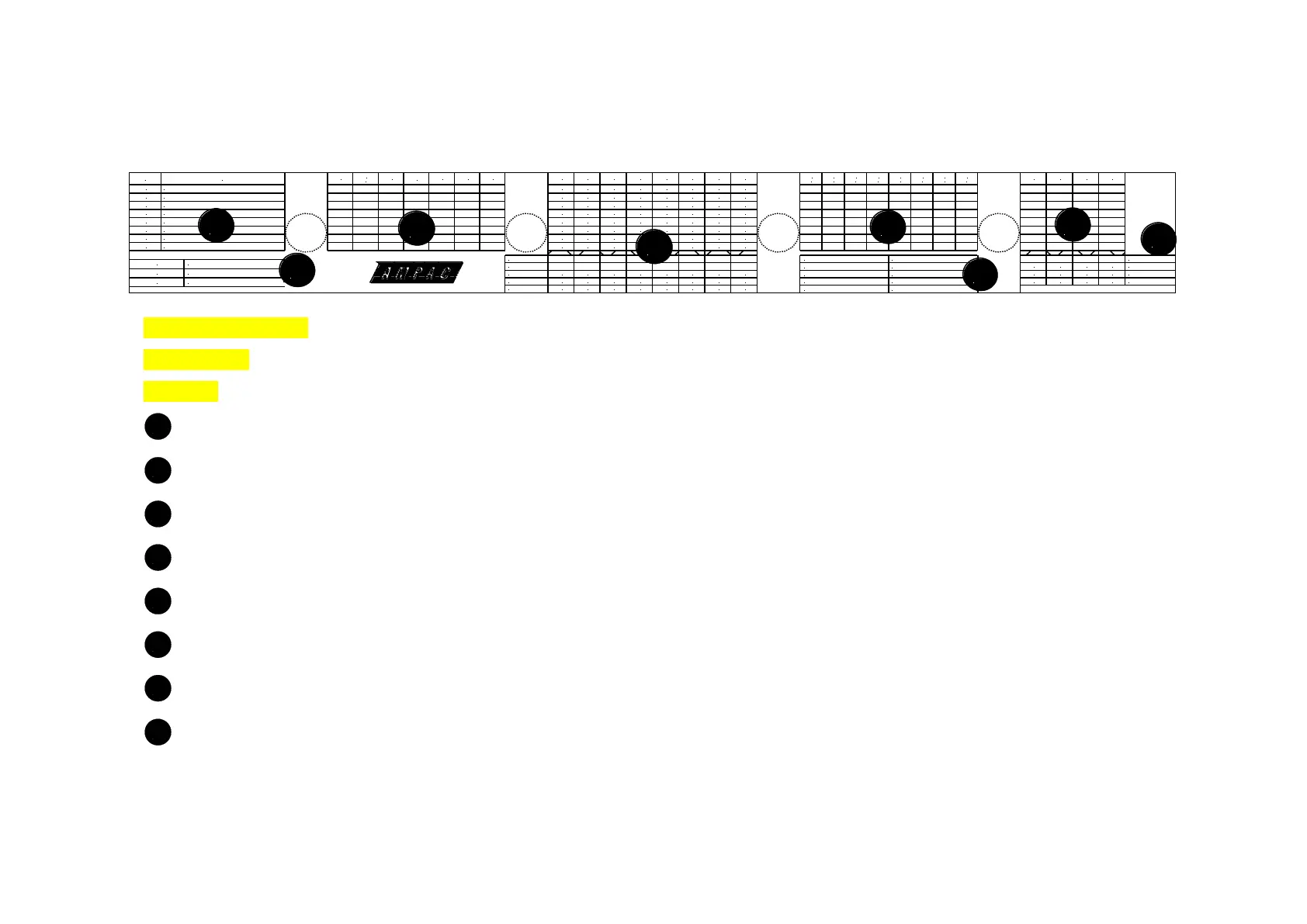
Instrucons to Installer
A, B, D, F and H Using a permanent marking pen cross out the condions that do not apply.
C, E, and G Using a permanent marking pen cross (X) the box for the opon that is set for the Zone.
Indicates the conguraon of each Zone Normal (NORM), AVF, Non-latching (NON), Self latching (SELF) Agent 1 (AT1), Agent 2 (AT2).
Indicates what EOL value has been selected, what Zone has MCP’s, and the number of LAM’s controlled by the FACP.
Indicates what Zones controls what Main Card Output.
Indicates if Alarm (A), Fault (F) or Isolate (I) controls the designated relay and the type of input it has.
Indicates what Zones control what Sounders.
Indicates the type of Agent Release ed the type and duraon of delay and the number Local Control Staons ed.
Indicates what Zone controls what Fan circuit.
Indicates the type of wire Funcon and whether or not latching and / or ACF Isolate is set.