Overview
3
ACR-5100 Acendo Core Administrators Guide
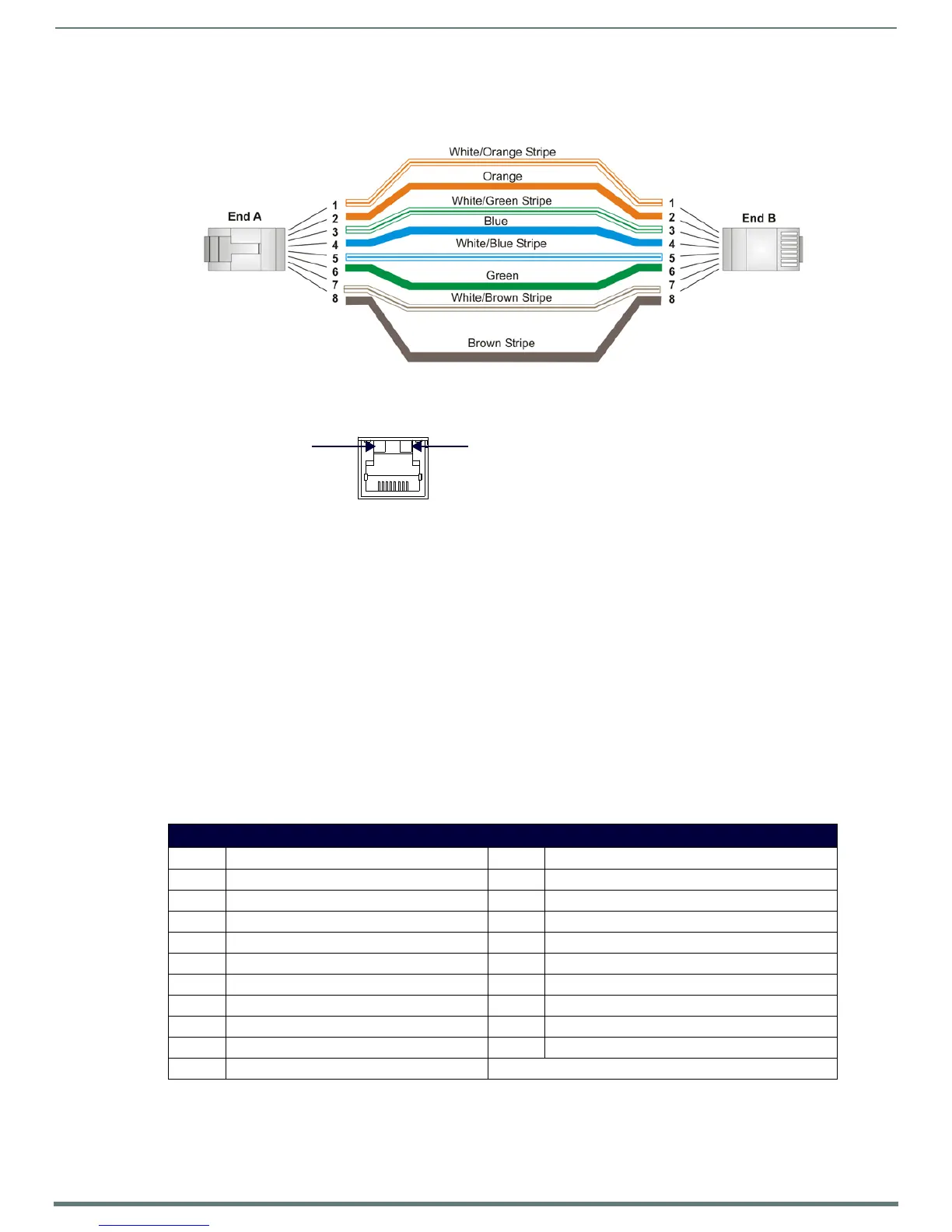
The rear panel features two 10/100/1000 Base-T RJ-45 (8P8C) LAN ports for network connection via Cat5 cable. Port2 is disabled
by default. FIG. 4 provides the pin outs and signals for the LAN connector and cable.
FIG. 5 describes the blink activity for the LAN connector and cable.
Dual HDMI Outputs
The rear panel features dual HDMI 2.0 video outputs that can be used for dual display or extended desktop as conf igured by the
system administrator in the Windows Display settings. These ports support the following:
CEC protocol for high-level control functions
Reading the E-EDID and first CEA Extension to determine the capabilities supported by the attached display device
Chooses a default minimal resolution if no E-EDID is received
Supports the following digital video output resolutions:
NOTE: Does not support dual displays with different resolutions. Both displays must use only one of these listed resolutions.
720p @ 60Hz
1080p @ 60Hz
4K @ 60Hz
Support an audio/video interface for transferring uncompressed video data and compressed or uncompressed audio data
from the HDMI source device to a display
The following table describes the pin-out configuration of the HDMI OUT connector:
FIG. 6 displays the pin locations for the HDMI connector:
Stereo Audio Line Output
FIG. 4 RJ-45 Wiring Diagram
FIG. 5 LAN Connector / LEDs
HDMI OUT Connector Pin-outs and Functions
Pin Signal Pin Signal
1 TMDS Data 2+ 11 TMDS Clock Shield
2 TMDS Data 2 Shield 12 TMDS Clock-
3TMDS Data 2- 13CEC
4 TMDS Data 1+ 14 Reserved, HEC Data
5 TMDS Data 1 Shield 15 SCL
6 TMDS Data 1- 16 SDA
7 TMDS Data 0+ 17 DDC/CEC/HEC Ground
8 TMDS Data 0 Shield 18 +5V Power (max 50mA)
9 TMDS Data 0- 19 Hot Plug Detect, HEC Data+
10 TMDS Clock+
ETHERNET
10/100
A L
Link LED (amber)
Activity LED (green)
lights when receiving or
transmitting LAN
data packets.
10/100/1000
Link speed:
Solid green - 1000
Blinking green - 100
Off - 10.
 Loading...