Maintenance and care
36 Edition 03.19 qTOWER
3
/ qTOWER
3
G
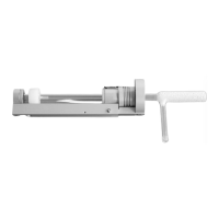
6. Note the code on the color module and
the position in which the color module
is to be installed.
7. Place the color module onto the free
position with the pin pointing down.
The silver pin points to the motor axis
and must engage in the centering hole
next to the large hole for the pin of the
color module.
Note: The correct position of the color
module is found quicker if you rotate
the color module slightly around its
own axis during insertion.
Press the color module down until it
rests flat on the rotor.
8. Screw on the color module with the M2 screws supplied.
9. Repeat this procedure for all color modules.
10. Close the remaining openings of the rotor with the color module dummy ele-
ments supplied.
Note:
The dummy elements seal the openings light-proof. If you want to install addi-
tional color modules at a later time, unscrew a dummy element from the rotor
and install the color module in its place.
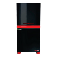
11. Rotate the wheel with the installed
color modules and check whether the
color modules grind against the upper
lid.
If this is the case, loosen the screw
connection of the color module, check
its position and retighten the screws.
NOTICE
Do not attempt to force a jammed color module into the correct position simply by tighten-
ing it further. The sensitive optics may be damaged.