14 I
I – 2 Milling Specific Operations
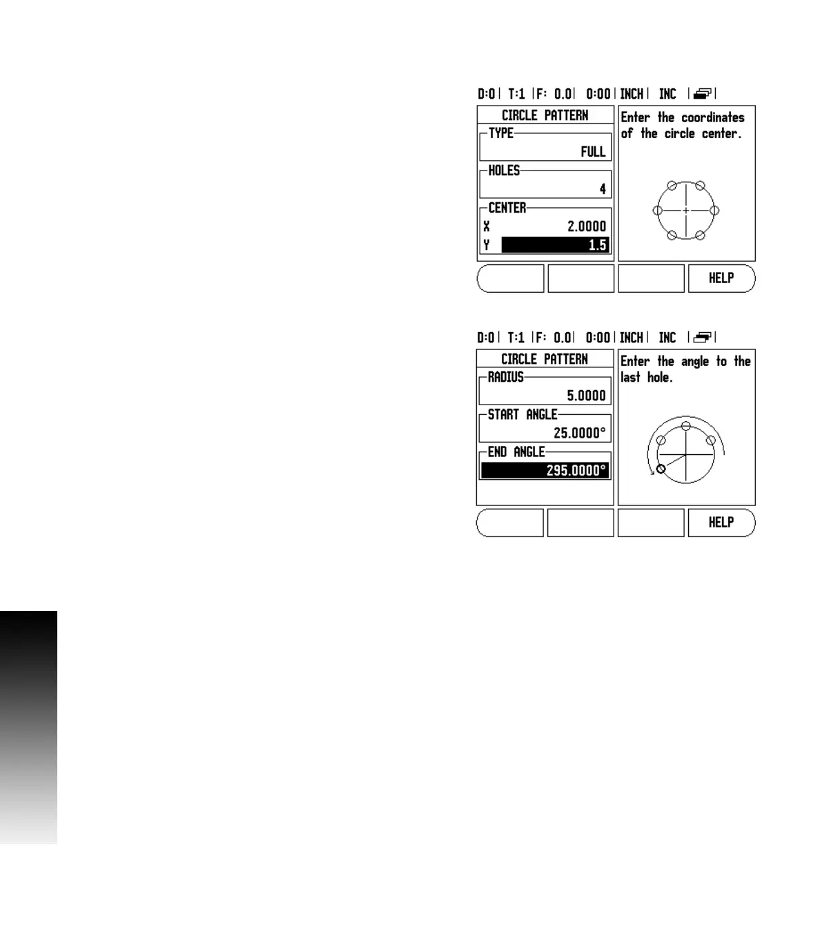
Example: Enter data and execute a circle pattern. See Fig. I.18 &
Fig. I.19.
Holes (no. of): 4
Coordinates of center: X = 2.0” / Y = 1.5”
Bolt circle radius: 5
S t a r t a n g l e : A n g l e b e t w e e n X a x i s a n d f i r s t h o l e : 2 5 °
Hole depth: Z = -0.25”
1st step: Enter data
Press CIRCLE PATTERN hard key.
Enter the type of circle pattern (full). Cursor to the next field.
Enter the number of holes (4).
Enter the X and Y coordinates of the circle center (X=2.0), (Y=1.5).
Cursor to the next field.
Enter the radius of the circle pattern (5).
Enter the start angle (25°).
Enter the end angle (295°) (this can only be changed if entering a
“segment”). The END ANGLE is defined as the angle from the
positive X-axis to the end of the pattern.
Enter the depth when needed. The depth of the hole is optional and
may be left blank. If not required, press ENTER.
Three views are available: Incremental DRO, Pattern Graphic, and
Absolute DRO. Press the VIEW soft key to toggle through the available
screens.
2nd step: Drill
Move to hole:
Traverse the X and Y axes until display value zero.
Drill:
Traverse to display value zero in the tool axis. After drilling, retract the
drill in tool axis.
Press the NEXT HOLE soft key.
Continue to drill the remaining holes in the same way.
When the pattern is complete, press the END soft key.
Fig. I.18 Beginning of Circle Pattern form
Fig. I.19 Page 2 of Circle Pattern Form