SECTION 6 PERFORMANCE TESTS
6-25
(4) Procedure
Step Procedure
1 Press the [Preset] key.
2 Operate All Cal.
3 Set the 69269A output to 2 GHz and 0 dBm.
4 Set the spectrum analyzer as shown below:
Center Freq.................................. 2.000 010 GHz
Span.......................................................... 25 kHz
Reference Level ........................................ 0 dBm
Attenuator................................................... 10 dB
RBW........................................................... 1 kHz
VBW .......................................................... 10 Hz
DET MODE ......................................... SAMPLE
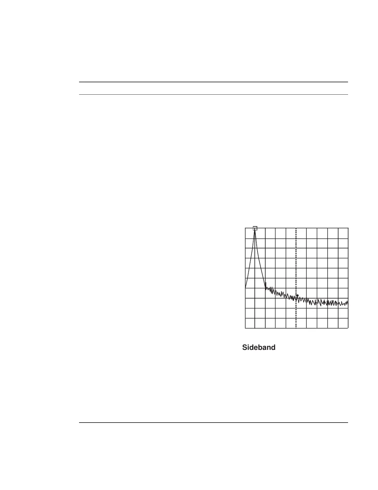
5 Press the [Peak Search] key to search for a peak
point so that the peak point on the signal trace is
included in the zone marker.
6 Press the [→ RLV] key to match the peak of the
signal trace to the top line (REF LEVEL) on the
screen.
7 After pressing the Measure key, select C/N Ratio
Measure.
8 Press the Meas On key to start C/N measurement.
9 Set Zone Width of Marker to Spot.
10 Press the [Marker] key, then turn the rotary knobto
move the zone marker to the right so that the zone
center frequency is 10.0 kHz.
11 Make sure that the C/N value is –95 dBc+20 logN
or less.
12 Repeat steps 3 through 11 for each frequency shown in the table on the next page.
CF : 2.000 010GHz Span : 25kHz
Sideband Noise Measurement