Installation GT3000
38 IMGT30017EN
Table 3A.5.2 Microprocessor Plus control terminal block
Warning: Do not connect voltage signals higher than 24 VDC to input connections
Function XM1 Label Description
3 RL1 Fault NO “Fault” 5A – 250VAC
4 RL1 Fault Com
44 RL1 Fault NC
1 RL2 Prog NO NO Configurable 5A – 250VAC
2 RL2 Prog Com COM
43 RL2 Prog NC NC
45 RL3 Prog NO COM Configurable 5A – 250VAC
Relay
46 RL3 Prog Com NO
5 Encoder +5V 5V-150mA SW1_A :OFF to connect external 12-
Isolated encoder
power supply
6 Encoder gnd 0V
7 Channel B With line driver encoder at 5V set : SW1_B to ON
8 Channel /B
(121 load resistance connected to encoder output signals )
9 Channel A
10 Channel /A
SW1_C to ON
(121 load resistance connected to encoder output signals )
11 Channel Z SW1_D to ON
Encoder
5-12-24V
1024 PPR
12 Channel /Z
(121 load resistance connected to encoder output signals )
13 DI 1 Start/Stop
The application of +24 VDC will cause the drive to start and ramp up in speed The
removal of +24 VDC will cause the drive to ramp down in speed and stop.
14 DI 2 Prog
Hi = ramp speed in the reverse direction – Low = ramp down
15 DI 3 Prog
16 DI 4 Prog
17 DI 5 Prog
Programmable
18 DI 6 Prog
19 DI 7 Prog
Isolated Digital Inputs
24V 8mA
20 DI 8 Drive enable
The application of +24 VDC will allow the drive to control the IGBTs.
The removal of +24 VDC will cause, after 0,5ms, the IGBTs to stop switching.
21 DO 4/DI 9(
1
)
*
Input 8mA /14V -10mA output – Programmable
Isolated Digital
Inputs/Outputs
22 DO 5/DI 10(
1
)
Digital Output
23 D0 6(
1
)
24V-10mA – Programmable, Protected with resettable fuse
24 DI supply+24V
100 mA -24V Isolated digital supply. Protected with resettable fuse
Digital I/O Power
Supply
25 DI /DO ground
0V Isolated digital supply
26 AI 1+
27 AI 1-
28 AI 2+
Isolated Analog
Inputs
29 AI 2-
Isolated Programmable Differential Inputs. Default: speed reference.
Inputs can be:
a)Through 5-10K potentiometer.(nominal 5K)
b) Voltage Signal 10V. Input Impedance 40 K
c) Current Signal 0/4-20mA. Input Impedance 475
34 AO 1
Programmable -0-10VDC or 10VDC-5mA
35 AO 2
36 AI/AO ground
0V
37 AO 3
Programmable-0-10VDC or 10VDC-5mA
38 AO 4
Isolated Analog
Outputs
39 AI/AO ground
0V
40 +10Vdc
+10VDC – 5mA
41 AI/AO ground
0V
Analog Reference
42 -10Vdc
-10VDC – 5mA
(
1)
) It is compulsory to use internal supply. External supply connected to terminal XM1-21/22/23 causes the damage
of the board.
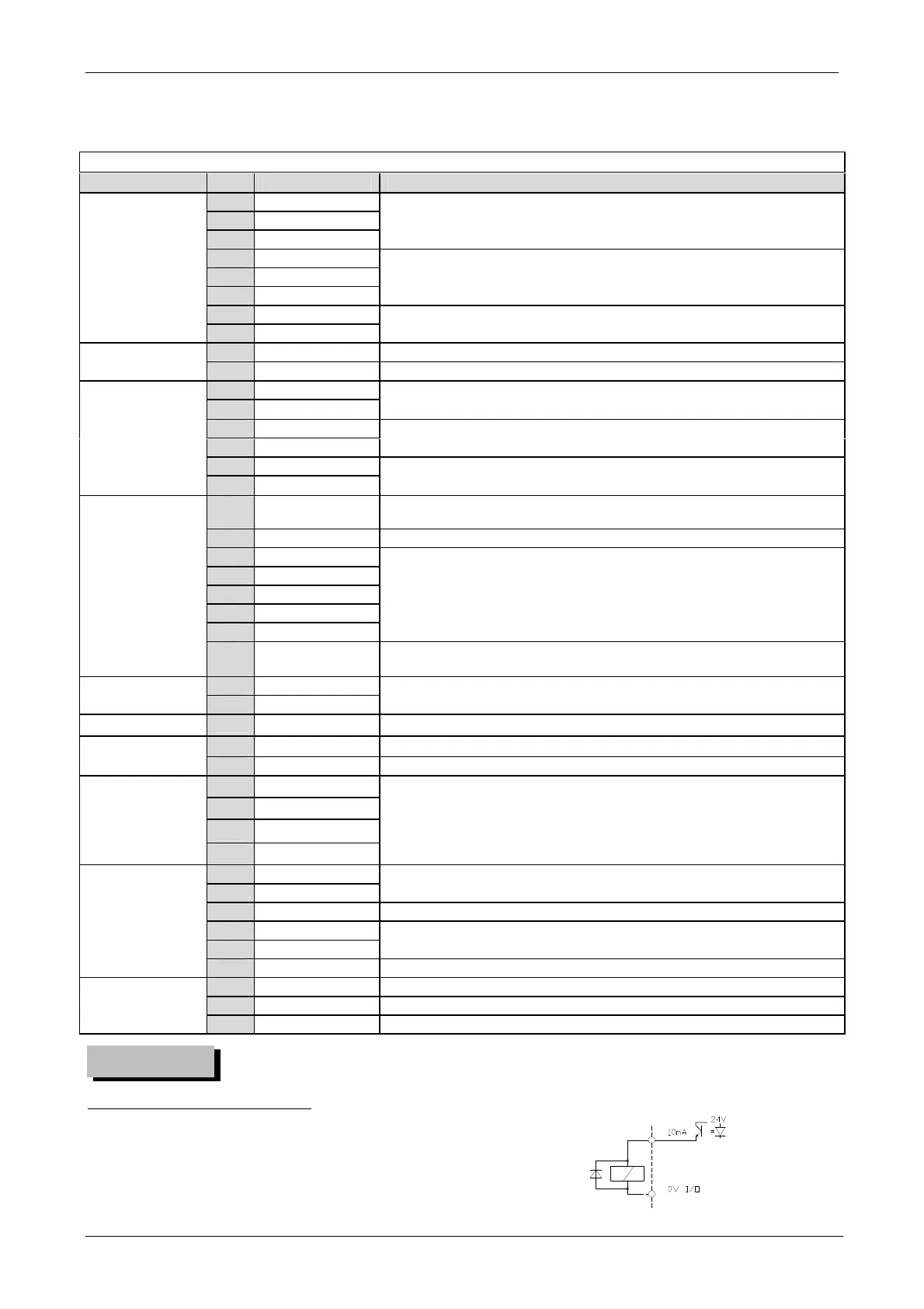
*
24V–10mA static output if the load is inductive type (relay coil), install a suitable diode in parallel
WARNING