E-ITN 30
Installation and service manual M2019/01a [EN]
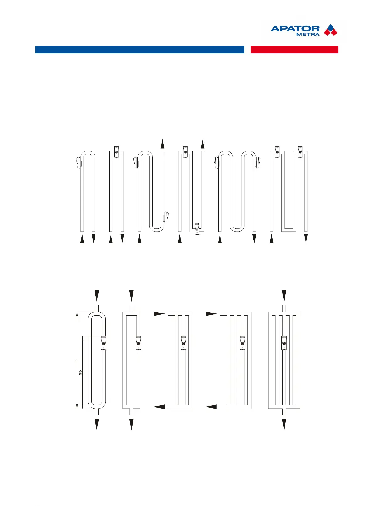
• 1x E-ITN 30 in the beginning of the tubular element curve
• in case of register welded into the frame, place E-ITN 30 on a horizontal tube
II. Bare tube with two curves
• 2x E-ITN 30 in the beginning of the upper curve and in the end of the lower curve
• in case of register welded into the frame, place E-ITN 30 on a horizontal tube
III. Bare tube with more than two curves
• 2x E-ITN 30 in the beginning of the first curve and in the end of the (last) upper curve
• in case of register welded into the frame, place E-ITN 30 on a horizontal tube
IV. Two or more small tubes connected in parallel
• 1x E-ITN 30 in 75% of the total height and nearest to the centre of tubular element
Note: If register does not match with those patterns, ask manufacturer for information.
30 / 46
 Loading...