E-ITN 30
Installation and service manual M2019/01a [EN]
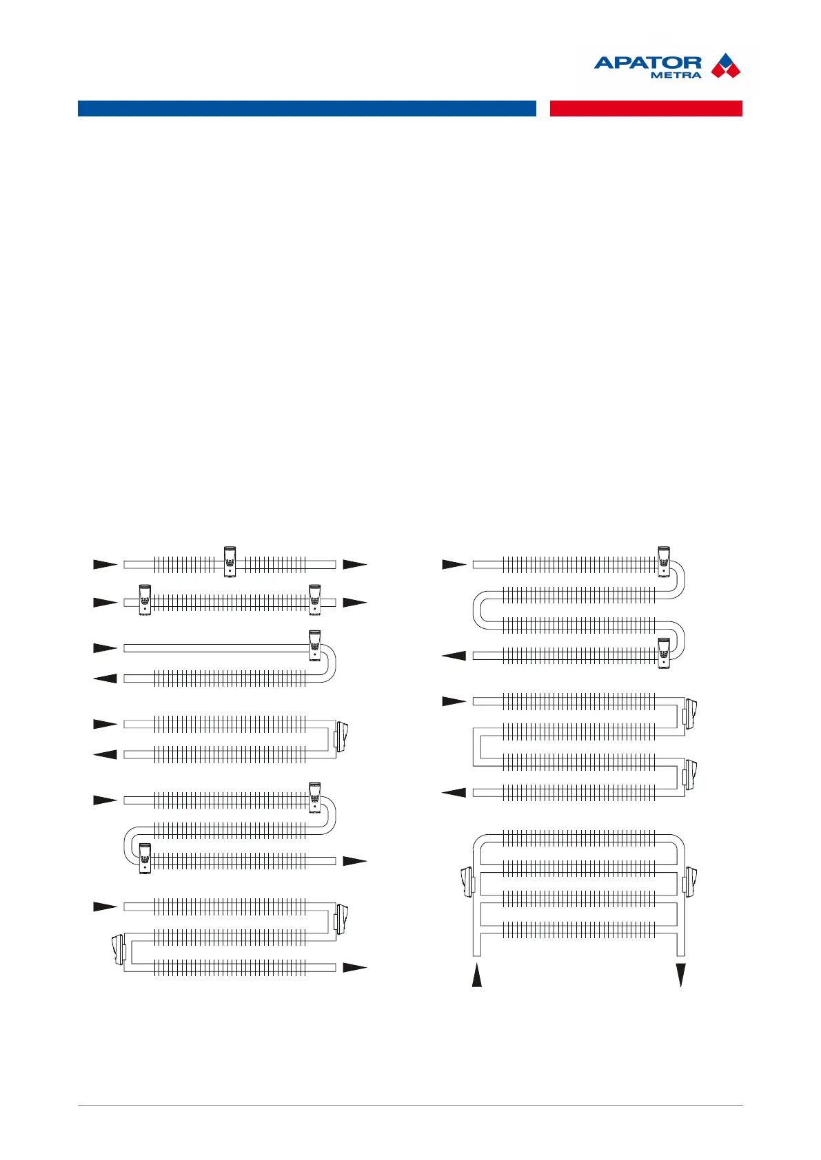
7.7.2. Proper E-ITN 30 installation on different register types
Horizontal tubes - bare and ribbed:
I. Ribbed tube straight with l ≤ 6 m and bare with l ≤ 12 m
• 1x E-ITN 30 in the centre of the tubular element
II. Ribbed tube straight with l > 6 m and bare with l > 12 m
• 2x E-ITN 30 in the beginning and the end of the tubular element
III. Ribbed or bare tube with one curve
• 1x E-ITN 30 in the beginning of the tubular element arch
• in case of register welded into the frame, place E-ITN 30 on a vertical tube
IV. Ribbed or bare tube with two curves
• 2x E-ITN 30 in the beginning of the upper curve and in the end of the lower curve
• in case of register welded into the frame, place E-ITN 30 on a vertical tube
V. Ribbed or bare tube with more than two curves
• 2x E-ITN 30 always in the beginning of the upper curve and in the end of the lower curve
• in case of register welded into the frame, place E-ITN 30 on a vertical tube
VI. Ribbed or bare tubes connected in parallel
• 2x E-ITN 30 into the middle or approximately to 75% (odd number of tubes) of the height of the
tubular element
Vertical bare tubes:
I. Bare tube with one curve
29 / 46

 Loading...