Portable Test Equipment
User’s Guide
PTE-UGFW56a-EN www.appliedp.com
Direction ..................... setting the sign of phase values in terms of rotation in vector
diagram; values are either Clockwise or Anticlockwise.
Relation ....................... setting the relation of current phase values; either current phase is
relative to voltage phase in given channel (Relative) or it is Absolute
and measured against 1
st
voltage channel
APPARENT POWER MEAS .... Settings of the way of calculation of overall apparent power
Method ........................ there are two methods of apparent power calculation:
- Scalar
- Vector
Control keys:
F1, ESC ...... Exit (return to previous page)
F3 .............. Load default values (only for parameters in shown page!)
F4 .............. Save parameter values of all Measurement Settings screens into memory
F5 .............. Switching between screens 1/3, 2/3 and 3/3
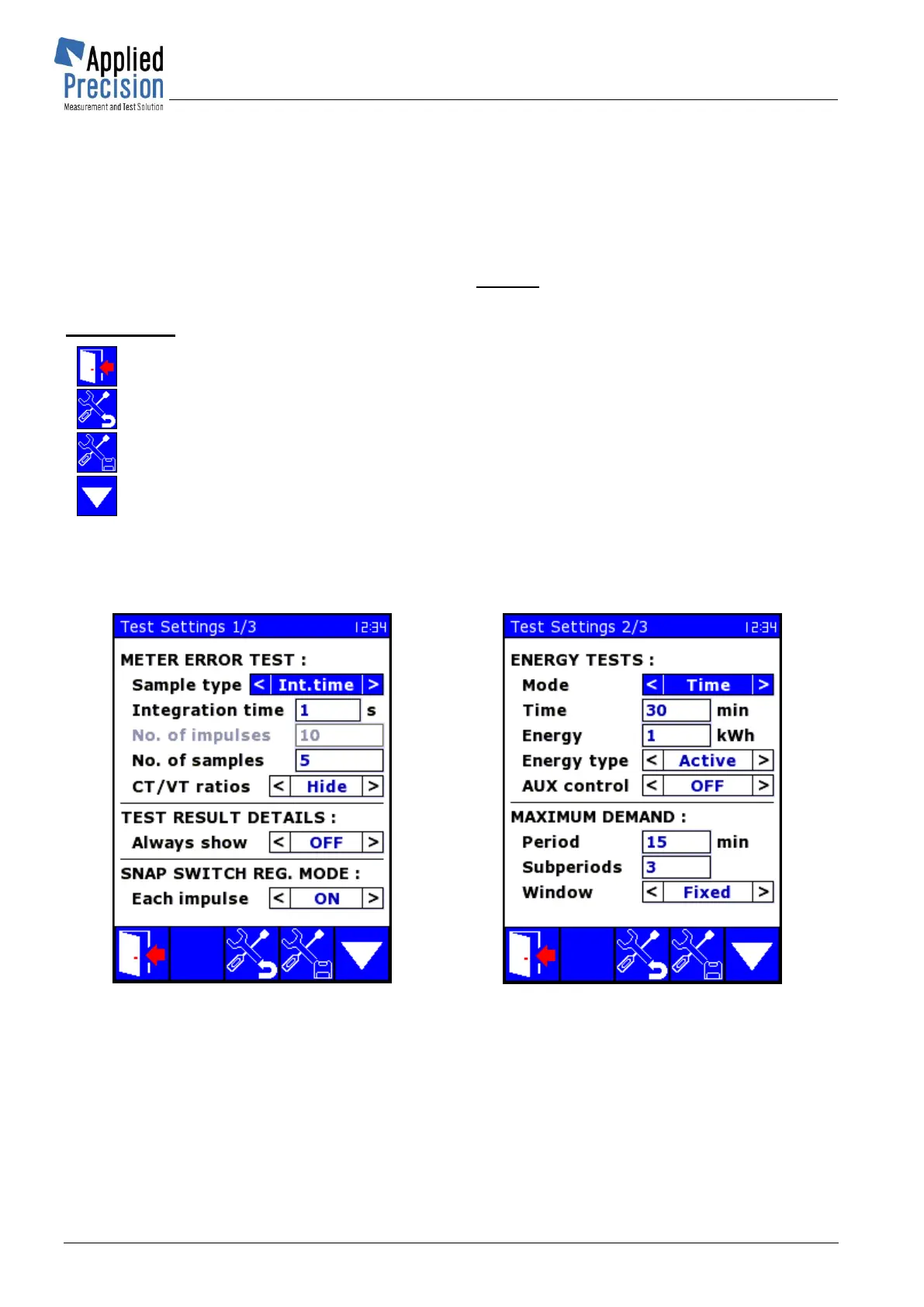
5.7.2 Test Settings
These pages contain parameters of testing mode.
Test Settings screen 1/3
* P45
Test Settings screen 2/3
* P89
METER ERROR TEST ............ Settings of meter testing
Sample type ................ determines the way of collecting samples, it’s either Impulses
(Integration time item is deactivated) or Int. time (No. of impulses
item is deactivated) or Time&Imp when both Impulses and Time can
be defined (both must be fulfilled to obtain one sample)
Integration time .......... minimum time between two measured error values of meter
[in seconds]
No. of impulses .......... Number of pulses required to calculate one sample
 Loading...