Portable Test Equipment
User’s Guide
PTE-UGFW56a-EN www.appliedp.com
2. Introduction
2.1 Device Panel Description
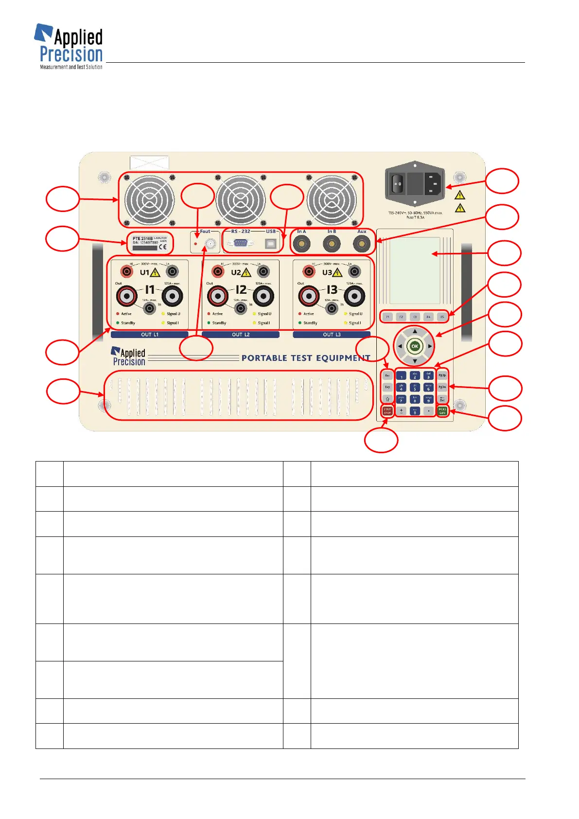
Figure 2 - PTE front panel
Display
- color graphical display
Function keys
- quick access to functions
Vents of fans
- 3 pcs of fans
Choice keys
- arrows and OK
Connectors for measuring accessory
- two universal ones and single AUX type
Exp, Shift, ESC key
- input of exponent of number, switching of
keys functionality, termination of functions
Name plate
- contains serial number and device type
Alphanumeric keypad
- keys 0-9 (a-z), decimal point, insertion of
plus/minus sign
Power connector with a switch
- connector is connected to 230V (CAT II)
mains network with standard cord with
PE
PgUp, PgDn, Del keys
- paging upwards and downwards
- deleting
Voltage and Current Outputs (CAT I)
– Hi and Lo terminals
- red is Hi and black is Lo; It is forbidden
to ground the Lo terminals in order not to
damage the PTE
MEAS / GEN key
- switching between generator and
measuring mode of device
Generator Start / Stop
- starting / stopping of signal generation
Communication connectors
- RS232, USB
Metrological LED
- red LED of impulse output
 Loading...