Portable Test Equipment
User’s Guide
www.appliedp.com PTE-UGFW56a-EN
5. Measuring Mode
Warnings
Do not touch the output terminals of the Product even if the display shows the
presence only non-lethal voltages or currents. There can be present lethal
voltages or currents due to error or connected meter.
This chapter describes user interface in measuring mode. Generator’s interface is described in
chapter 3.
After switching into measuring mode always last used screen appears or Load Values screen if power
on just happened.
5.1 Main Measurement
Content of main measurement page depends on type of connected sensors:
Load Values .......................... if one voltage and one current sensor are connected
Actual Values (I) .................... if one current sensor is connected
Actual Values (U) .................. if one voltage sensor is connected
Actual Values (I+I) ................. if two current sensors are connected
Actual Values (U+U) ............. if two voltage sensors are connected
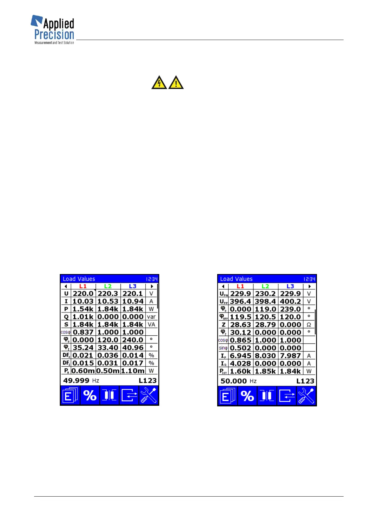
5.1.1 Load Values
Page Load Values shows actual measured and calculated values of load point when one current and
one voltage measurement sensors are used.
Load Values screen LVa
* P01
Load Values screen LVb
* P70
 Loading...