P44x/EN AD/E44 Update Documentation
Page 64/82
MiCOM P441, P442 & P444
9.9.3.1
Configure GOOSE settings
The GOOSE Scheme Logic editor is used to enrol devices and also to provide support for
mapping the Digital Data Bus signals (from the Programmable Scheme Logic) onto the
UCA2.0 GOOSE bit-pairs.
If the relay is interested in data from other UCA2.0 GOOSE devices, their "Sending IED"
names are added as ’enrolled’ devices within the GOOSE Scheme Logic. The GOOSE
Scheme Logic editor then allows the mapping of incoming UCA2.0 GOOSE message bit-
pairs onto Digital Data Bus signals for use within the Programmable Scheme Logic.
UCA2.0 GOOSE is normally disabled in the MiCOM Px40 products and is enabled by
downloading a GOOSE Scheme Logic file that is customised.
9.9.3.2
Device naming
Each UCA2.0 GOOSE enabled device on the network transmits messages using a unique
"Sending IED" name.
Select Rename from the Edit menu to assign the "Sending IED" name to the device.
9.9.3.3
Enrolling IED’s
Enrolling a UCA2.0 GOOSE device is done through the Px40s GOOSE Scheme Logic. If a
relay is interested in receiving data from a device, the "Sending IED" name is simply added
to the relays list of ’interested devices’.
Select New Enrolled IED from the Edit menu and enter the GOOSE IED name (or "Sending
IED" name) of the new device.
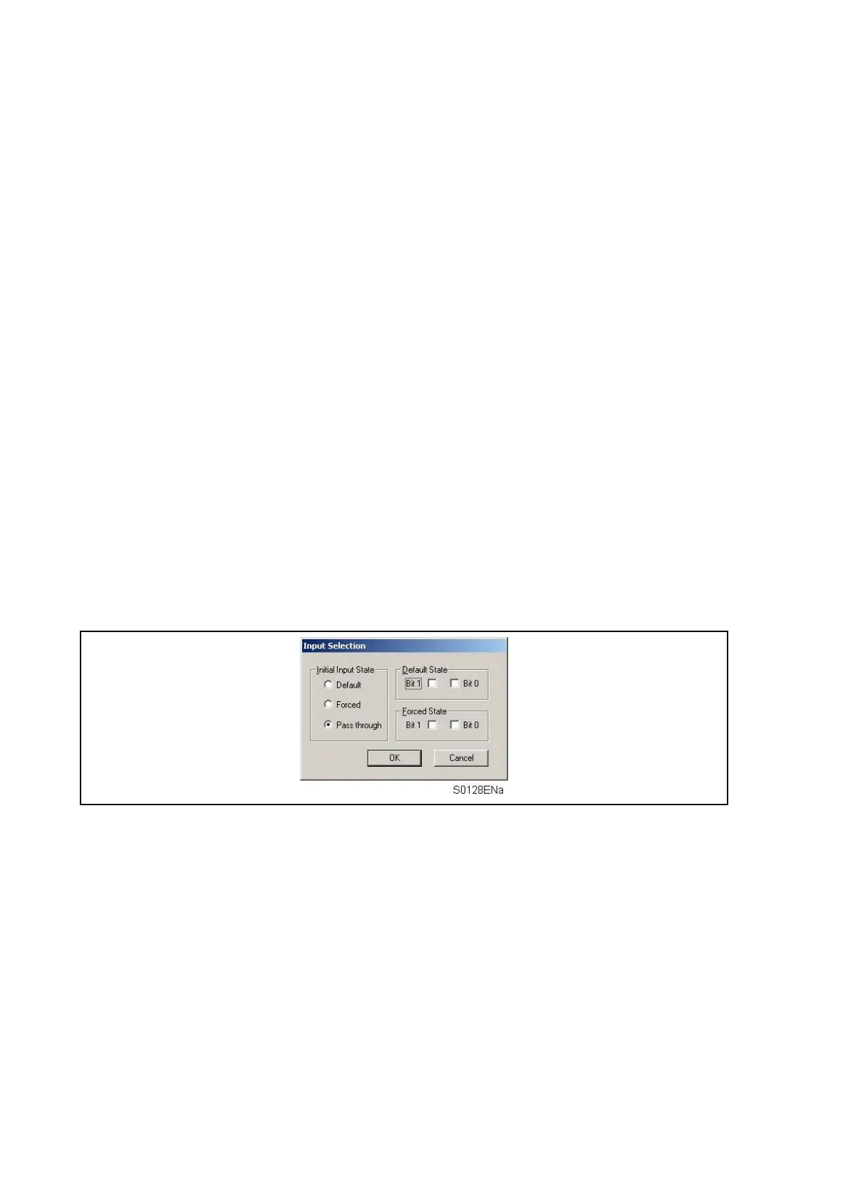
Enrolled IED’s have GOOSE In settings containing DNA (Dynamic Network Announcement)
and User Status bit-pairs. These input signals can be configured to be passed directly
through to the Virtual Input gates or be set to a forced or default state before processing by
the Virtual Input logic.
The signals in the GOOSE In settings of enrolled IED’s are mapped to Virtual Inputs by
selecting New Mapping from the Edit menu. Refer to section below for use of these signals
in logic.
9.9.3.4
GOOSE In settings
Virtual inputs
The GOOSE Scheme Logic interfaces with the Programmable Scheme Logic by means of
32 Virtual Inputs. The Virtual Inputs are then used in much the same way as the Opto Input
signals.
The logic that drives each of the Virtual Inputs is contained within the relay’s GOOSE
Scheme Logic file. It is possible to map any number of bit-pairs, from any enrolled device,
using logic gates onto a Virtual Input.


 To Next Page