Update Documentation P44x/EN AD/E44
MiCOM P441, P442 & P444
Page 65/82
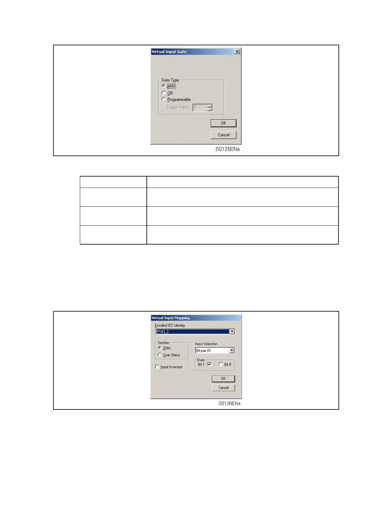
The following gate types are supported within the GOOSE Scheme Logic:
Gate Type Operation
AND
The GOOSE Virtual Input will only be logic 1 (i.e. ON) when all bit-
pairs match the desired state.
OR
The GOOSE Virtual Input will be logic 1 (i.e. ON) when any bit-pair
matches its desired state.
PROGRAMMABLE
The GOOSE Virtual Input will only be logic 1 (i.e. ON) when the
majority of the bit-pairs match their desired state.
To add a Virtual Input to the GOOSE logic configuration, select New Virtual Input from the
Edit menu and configure the input number. If required, the gate type can be changed once
input mapping to the Virtual Input has been made.
Mapping
GOOSE In signals from enrolled IED’s are mapped to logic gates by selection of the required
bit-pair from either the DNA or User Status section of the inputs.
The value required for a logic 1 or ON state is specified in the State box. The input can be
inverted by checking Input Inversion (equivalent to a NOT input to the logic gate).
GOOSE Out settings
The structure of information transmitted via UCA2.0 GOOSE is defined by the ’Protection
Action’ (PACT) common class template, defined by GOMFSE (Generic Object Models for
Substation and Feeder Equipment).
A UCA2.0 GOOSE message transmitted by a Px40 relay can carry up to 96 Digital Data Bus
signals, where the monitored signals are characterised by a two-bit status value, or "bit-pair".
The value transmitted in the bit-pair is customisable although GOMFSE recommends the
following assignments:


 To Next Page