P44x/EN AD/E44 Update Documentation
Page 72/82
MiCOM P441, P442 & P444
9.10.4 InterMiCOM Settings
The settings necessary for the implementation of InterMiCOM are contained within two
columns of the relay menu structure. The first column entitled “INTERMICOM COMMS”
contains all the information to configure the communication channel and also contains the
channel statistics and diagnostic facilities. The second column entitled “INTERMICOM
CONF” selects the format of each signal and its fallback operation mode. The following
tables show the relay menus including the available setting ranges and factory defaults.
Setting Range
Menu Text Default Setting
Min Max
Step Size
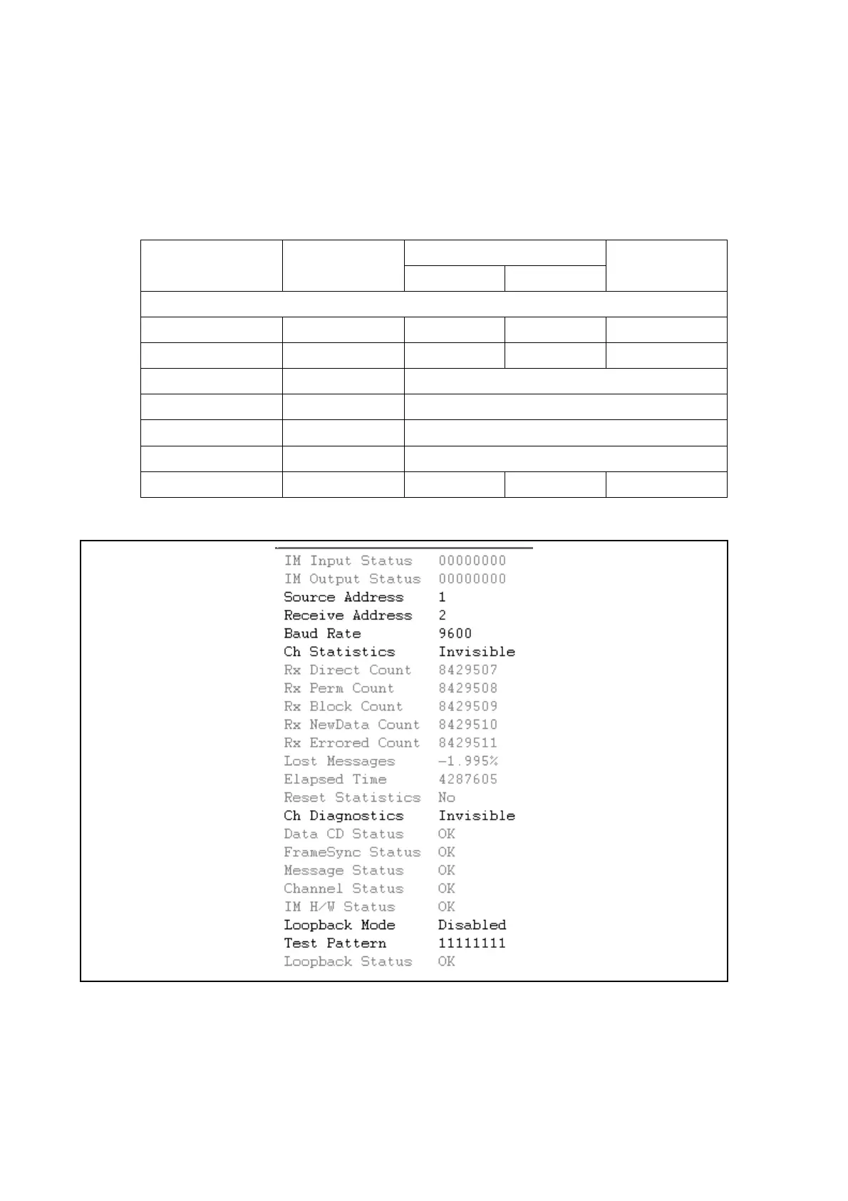
INTERMICOM COMMS
Source Address 1 1 10 1
Receive Address 2 1 10 1
Baud Rate 9600 600 / 1200 / 2400 / 4800 / 9600 / 19200
Ch Statistics Invisible Invisible / Visible
Ch Diagnostics Invisible Invisible / Visible
Loopback Mode Disabled Disabled / Internal / External
Test pattern 11111111 00000000 11111111 -
TABLE 3 : INTERMiCOM GENERIC COMMUNICATIONS SET-UP


 To Next Page