43
8126F–AVR–05/12
ATtiny13A
This is useful for keeping the Watchdog Timer security while using the interrupt. To stay in Inter-
rupt and System Reset Mode, WDTIE must be set after each interrupt. This should however not
be done within the interrupt service routine itself, as this might compromise the safety-function of
the Watchdog System Reset mode. If the interrupt is not executed before the next time-out, a
System Reset will be applied.
Note: 1. WDTON fuse set to “0“ means programmed and “1“ means unprogrammed.
• Bit 4 – WDCE: Watchdog Change Enable
This bit is used in timed sequences for changing WDE and prescaler bits. To clear the WDE bit,
and/or change the prescaler bits, WDCE must be set.
Once written to one, hardware will clear WDCE after four clock cycles.
• Bit 3 – WDE: Watchdog System Reset Enable
WDE is overridden by WDRF in MCUSR. This means that WDE is always set when WDRF is
set. To clear WDE, WDRF must be cleared first. This feature ensures multiple resets during con-
ditions causing failure, and a safe start-up after the failure.
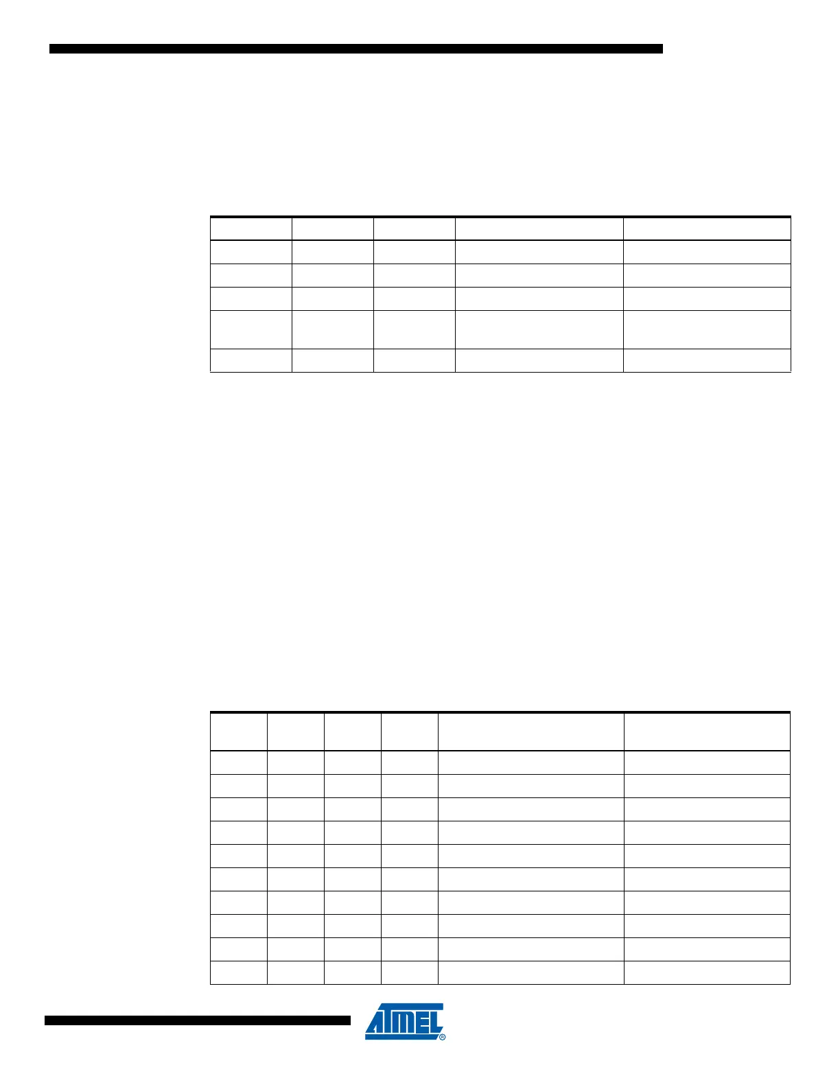
• Bit 5, 2:0 – WDP[3:0]: Watchdog Timer Prescaler 3, 2, 1 and 0
The WDP[3:0] bits determine the Watchdog Timer prescaling when the Watchdog Timer is run-
ning. The different prescaling values and their corresponding time-out periods are shown in
Table 8-2 on page 43.
Table 8-1. Watchdog Timer Configuration
WDTON
(1)
WDE WDTIE Mode Action on Time-out
1 0 0 Stopped None
1 0 1 Interrupt Mode Interrupt
1 1 0 System Reset Mode Reset
111
Interrupt and System Reset
Mode
Interrupt, then go to System
Reset Mode
0 x x System Reset Mode Reset
Table 8-2. Watchdog Timer Prescale Select
WDP3 WDP2 WDP1 WDP0
Number of WDT Oscillator
Cycles
Typical Time-out at
V
CC
= 5.0V
0000 2K (2048) cycles 16 ms
0001 4K (4096) cycles 32 ms
0010 8K (8192) cycles 64 ms
0011 16K (16384) cycles 0.125 s
0100 32K (32768) cycles 0.25 s
0101 64K (65536) cycles 0.5 s
0110 128K (131072) cycles 1.0 s
0111 256K (262144) cycles 2.0 s
1000 512K (524288) cycles 4.0 s
10011024K (1048576) cycles 8.0 s