33
7679H–CAN–08/08
AT90CAN32/64/128
• Bit 3..2 – SRW11, SRW10: Wait-state Select Bits for Upper Sector
The SRW11 and SRW10 bits control the number of wait-states for the upper sector of the exter-
nal memory address space, see Table 4-4.
• Bit 1..0 – SRW01, SRW00: Wait-state Select Bits for Lower Sector
The SRW01 and SRW00 bits control the number of wait-states for the lower sector of the exter-
nal memory address space, see Table 4-4.
Note: 1. n = 0 or 1 (lower/upper sector).
For further details of the timing and wait-states of the External Memory Interface, see Figures
4-6 through Figures 4-9 for how the setting of the SRW bits affects the timing.
4.5.7 External Memory Control Register B – XMCRB
• Bit 7– XMBK: External Memory Bus-keeper Enable
Writing XMBK to one enables the bus keeper on the AD7:0 lines. When the bus keeper is
enabled, it will ensure a defined logic level (zero or one) on AD7:0 when they would otherwise
be tri-stated. Writing XMBK to zero disables the bus keeper. XMBK is not qualified with SRE, so
even if the XMEM interface is disabled, the bus keepers are still activated as long as XMBK is
one.
• Bit 6..4 – Reserved Bits
These are reserved bits and will always read as zero. When writing to this address location,
write these bits to zero for compatibility with future devices.
• Bit 2..0 – XMM2, XMM1, XMM0: External Memory High Mask
When the External Memory is enabled, all Port C pins are default used for the high address byte.
If the full address space is not required to access the External Memory, some, or all, Port C pins
can be released for normal Port Pin function as described in Table 4-5. As described in “Using
all 64KB Locations of External Memory” on page 35, it is possible to use the XMMn bits to
access all 64KB locations of the External Memory.
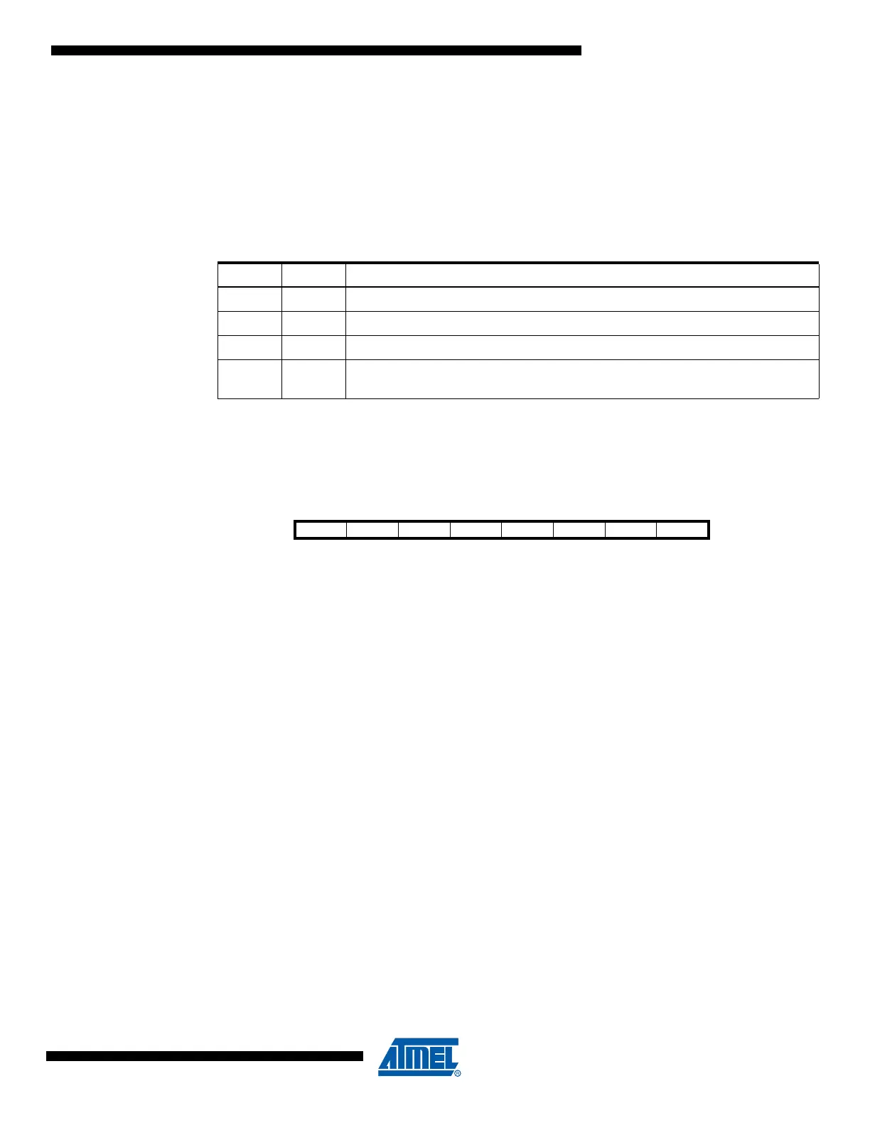
Table 4-4. Wait States
(1)
SRWn1 SRWn0 Wait States
0 0 No wait-states
0 1 Wait one cycle during read/write strobe
1 0 Wait two cycles during read/write strobe
11
Wait two cycles during read/write and wait one cycle before driving out new
address
Bit 76543210
XMBK – – – – XMM2 XMM1 XMM0 XMCRB
Read/Write R/W R R R R R/W R/W R/W
Initial Value00000000

 Loading...


