INSTALLATION and POWER
page 1 – 2
D-70 / Apr 2000
Installation and Power
Unpacking the Console
The D-70 console is shipped as three packages. One carton contains
the console and documentation, second carton contains the Power
Supply and connecting cable, and third carton contains input daughter
cards.
Countertop Mounting
The D-70 digital audio console is designed for countertop mount-
ing. Console placement should avoid proximity to any electromagnetic
fields, such as large power transformers, motors, and fluorescent
lighting fixtures. If you will be securing the console to the counter top,
you may want to pre-drill the mounting holes (see sketch for 20 and 28
position frames below).
Set the console in place on the counter, and remove the screws that
hold down the first and the last modules in place (two per module).
Carefully remove those modules from the frame. Attach the console
mainframe to the counter top, using the holes provided in the bottom
of the chassis and screws appropriate to the counter material, and
reinstall the removed modules.
The console extends approximately 7 3/4” above the countertop at
the meterbridge. Also, the rear panel requires 3 1/2” of clearance
behind the console to open fully.
Do not connect the D-70 console to its power supply (and do not
connect the power supply to the AC power line) until instructed to
do so.
NOTE: This console contains
static-sensitive devices. Nor-
mal precautions against static
discharge should be observed
when handling individual
modules.
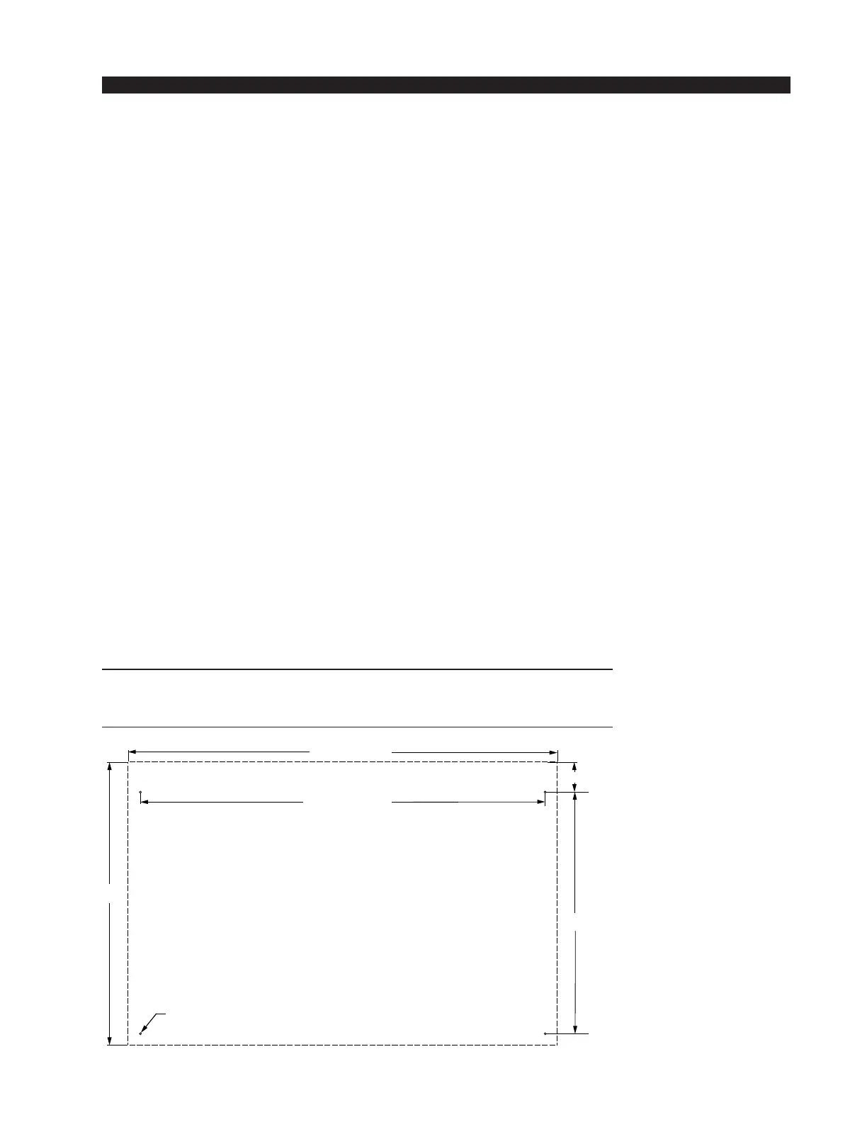
NOTE: Dimensions shown
are for 20 position main-
frames; 28 position frames
dimensions are shown in pa-
rentheses().
D-70 / Aug 2000
19.900
28.488 (40.568)
17.000
D=.171"; use #8 screws
Dashed line is console outline
2.100
30.210 (42.29)