page 4 – 2
D-70 / Apr 2000
CONTROL ROOM MODULE
Control Room Module
(CRD-70)
Module Overview
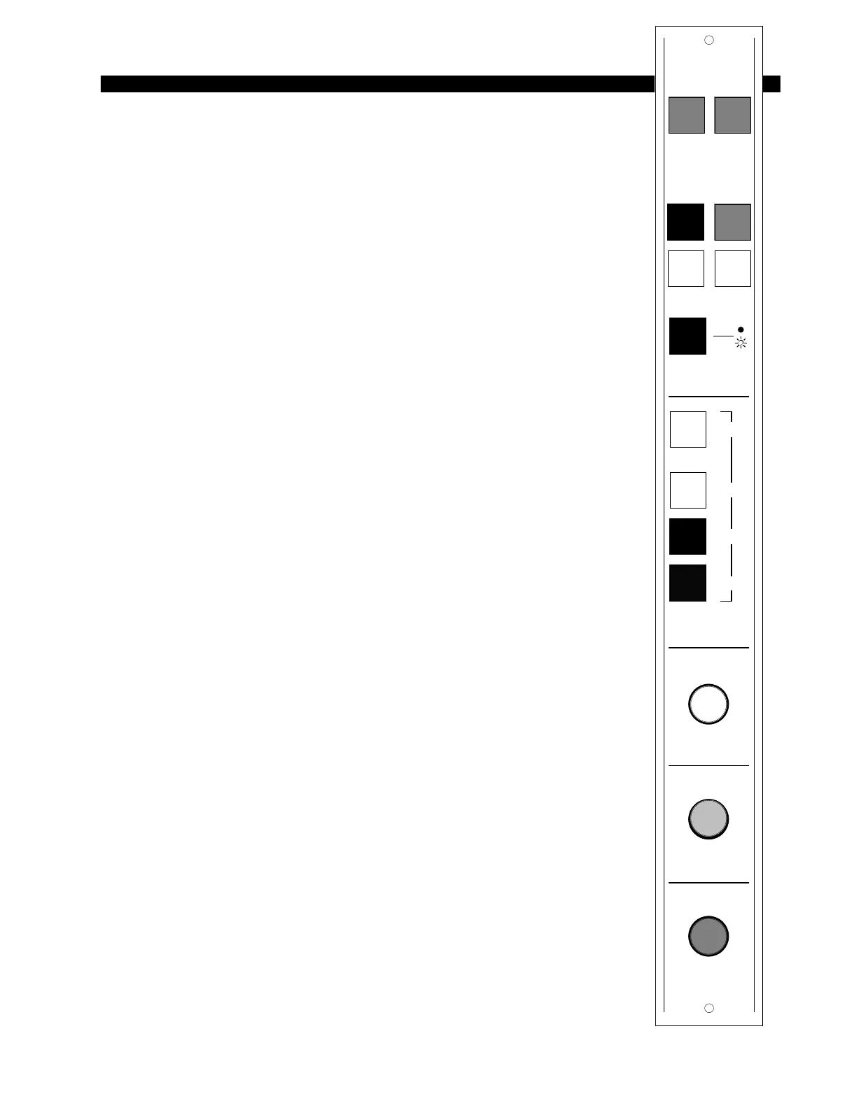
The CRD-70 module is the D-70 console operator’s monitor module.
It allows him to listen to the console’s four stereo outputs (PGM, AUD,
AUX1 & AUX2) as well as two external stereo line level inputs brought
directly into the module via the CRD-70/1 rear panel.
The CRD-70 also houses console HEADPHONE and CONTROL
ROOM circuits, which follow the source selection switches.
There are two types of headphone output: the +4dBu balanced output at the
module’s rear panel (CRD-70/2) six-conductor connector (pre-level control),
and the headphone jack mounted right on the front of the lower mainframe pan,
which is actually the output from a built-in headphone amplifier. It is this built-
in amp that is controlled by the module’s front panel HEADPHONE level
control.
The CUE master level control sets the level of the console’s cue signal.
Whenever CUE is activated elsewhere on the console (stereo line inputs, the
superphone module, or for studio talkback) its signal will appear at the
console’s built-in cue speaker mounted in the meterbridge. Depending on how
the CRD-70 module has been programmed, cue can also interrupt the control
room monitor speaker and/or the console operator’s headphone. The way Cue
interrupts the module’s headphone and CR outputs is determined by internal
PCB-mounted jumpers. See “Cue Interrupt” on next page.
The D-70 digital audio console is provided with a serial interface port.
Activating the pushbutton LOC/REM switch will enable the remote serial
interface to the console, and deactivating the switch will disable the remote
serial interface. (For more details see Chapter 6.)
At the center of the module are the timer control buttons (the timer
display is mounted in the righthand end of the console meterbridge):
AUTO – enables timer restart functions from programmed input modules
S/S – Start/Stop
RESET - return to zero (if the timer is stopped it will hold at zero; if it is
running it will reset to zero and immediately begin counting up).
HOLD – when held down freezes the timer display (the counter keeps on
going); when released the display catches up to the current count.
All user wiring to and from the CRD-70 module takes place at
six-conductor connectors mounted on the module’s rear panels. The two
rear panels, MONITOR 1 and MONITOR 2, are shared by the CRD-70
and SCD-70 modules. All audio connections are stereo line level analog
signals (+4dBu balanced).
EXT 1
10
9
8
7
64
3
2
1
0
5
CUE
10
9
8
7
64
3
2
1
0
5
HDPN
TIMER
10
9
8
7
64
3
2
1
0
5
CR
PGM AUD
AUX1 2AUX
SOURCE
EXT 2
S/S
RST
HOLD
AUTO
LOC
REM
D-70 / May 2003