page 4 – 3
D-70 / Apr 2000
CONTROL ROOM MODULE
Internal Programming Options
There are five user-programmable jumpers for CRD-70 located on the
lower center of the Processor Board PR-70 PCB to set various cue interrupt
modes and cue mute (see below).
Cue Interrupt
Jumpers J10-J13 determines how the console’s Cue function will
interrupt regular monitor signals:
J10 sends cue to CR left
J11 sends cue to CR right
J12 sends cue to HDPN left*
J13 sends cue to HDPN right*
Cue Mute
As Cue is also fed to the console’s built-in meterbridge speakers, where
it can easily be picked up by the console operator’s microphone, there is
provision to mute Cue whenever that mic is live (i.e., whenever the control
room mute function is activated).
Jumper J14 will mute cue whenever CR is muted (this is the factory
default setting)
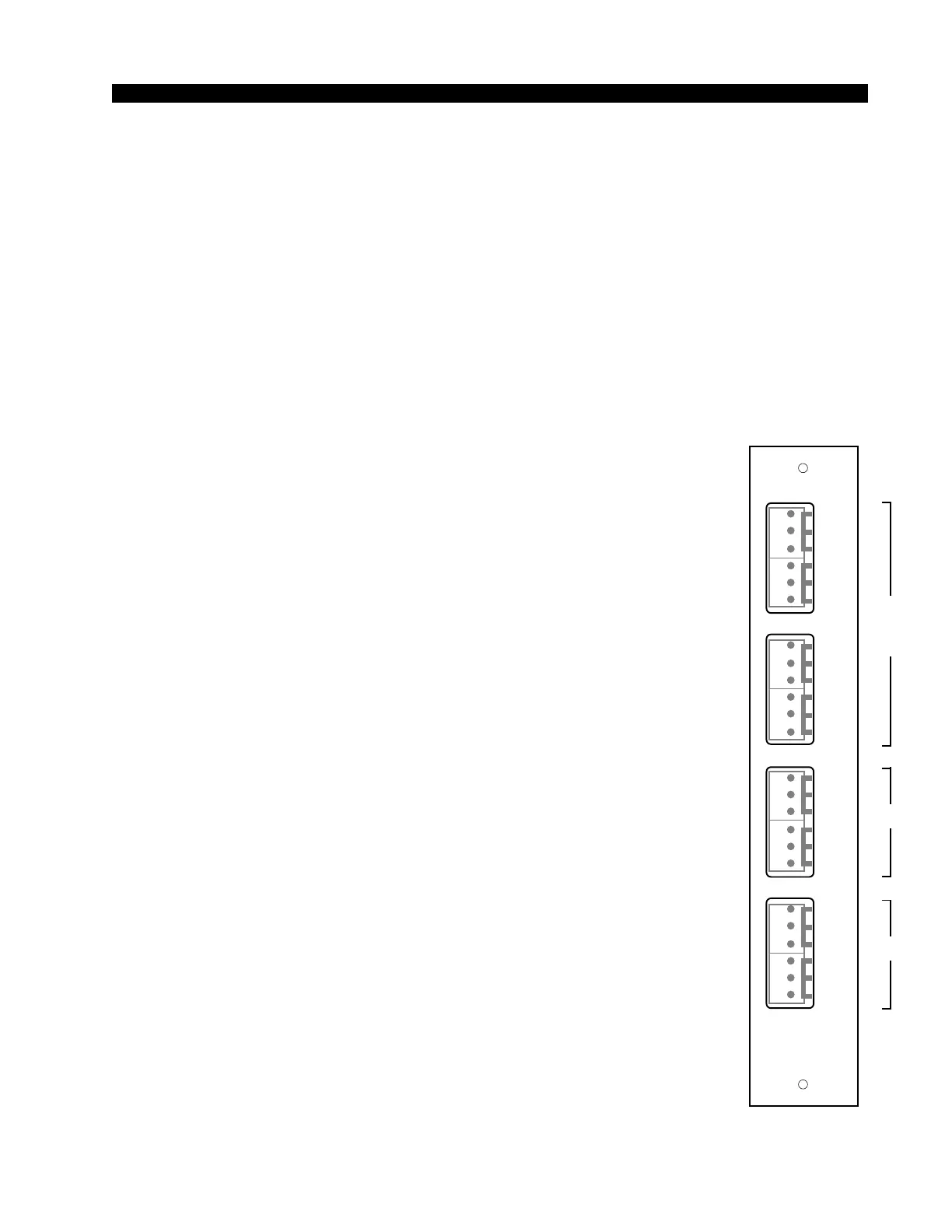
Hook-Ups
As stated before, all user wiring to and from the CRD-70 module takes
place at six-conductor connectors mounted on the module’s rear panels.
The two panels, MONITOR 1 and MONITOR 2, are shared with the SCD-
70 module.
CRD-70/1 Rear Panel Audio Connections:
Includes external stereo inputs and control room outputs. All audio
signals are +4dBu balanced, analog stereo.
Pin 6 – Lt Ext 1 In LO
Pin 5 – Lt Ext 1 In SH
Pin 4 – Lt Ext 1 In HI
Pin 3 – Rt Ext 1 In LO
Pin 2 – Rt Ext 1 In SH
Pin 1 – Rt Ext 1 In HI
Pin 6 – Lt Ext 2 In LO
Pin 5 – Lt Ext 2 In SH
Pin 4 – Lt Ext 2 In HI
Pin 3 – Rt Ext 2 In LO
Pin 2 – Rt Ext 2 In SH
Pin 1 – Rt Ext 2 In HI
Pin 6 – Lt CR Out LO
Pin 5 – Lt CR Out SH
Pin 4 – Lt CR Out HI
*factory default settings
CRD-70/1
Rear Panel
EX1
L
S
H
EX2
LT
RT
L
S
H
L
S
H
L
S
H
LT
RT
CR
L
S
H
ST
LT
RT
L
S
H
L
S
H
L
S
H
LT
RT
MONITOR
1
1
2
3
4
5
6
1
2
3
4
5
6
1
2
3
4
5
6
1
2
3
4
5
6
D-70 / Jan 2001
D-70 / May 2003
SCD-70
CRD-70
CRD-70
and
SCD-70