page 2 – 6
D-70 / Apr 2000
INPUT MODULE
This closure can be used to control an externally powered tally light
that requires a continuous closure to function. Or an external tally light
(i.e., LED) can be powered from the input module by connecting the
external LED to +5V Digital (Pin 9 or Pin 10) and the On Tally port.
In either case, current should not exceed 30 milliamps.
Off Tally
Identical to “On Tally” (preceding), only this tally is active when
the module is OFF. Off Tally A is Pin 3.
Tally B
Provides a remote indication that the module’s B source has been
selected. This control function provides a continuous closure (open
collector) between Pin11 (Tally B) and Digital Ground (Pins 7, 8 or 12)
whenever the B source is selected.
This closure can be used to control an externally powered tally light
that requires a continuous closure to function. An external tally light
(i.e., LED) can be powered from the input module by connecting the
external LED to +5V Digital (Pin 9 or Pin 10) and the B Tally port. In
either case, current should not exceed 30 milliamps.
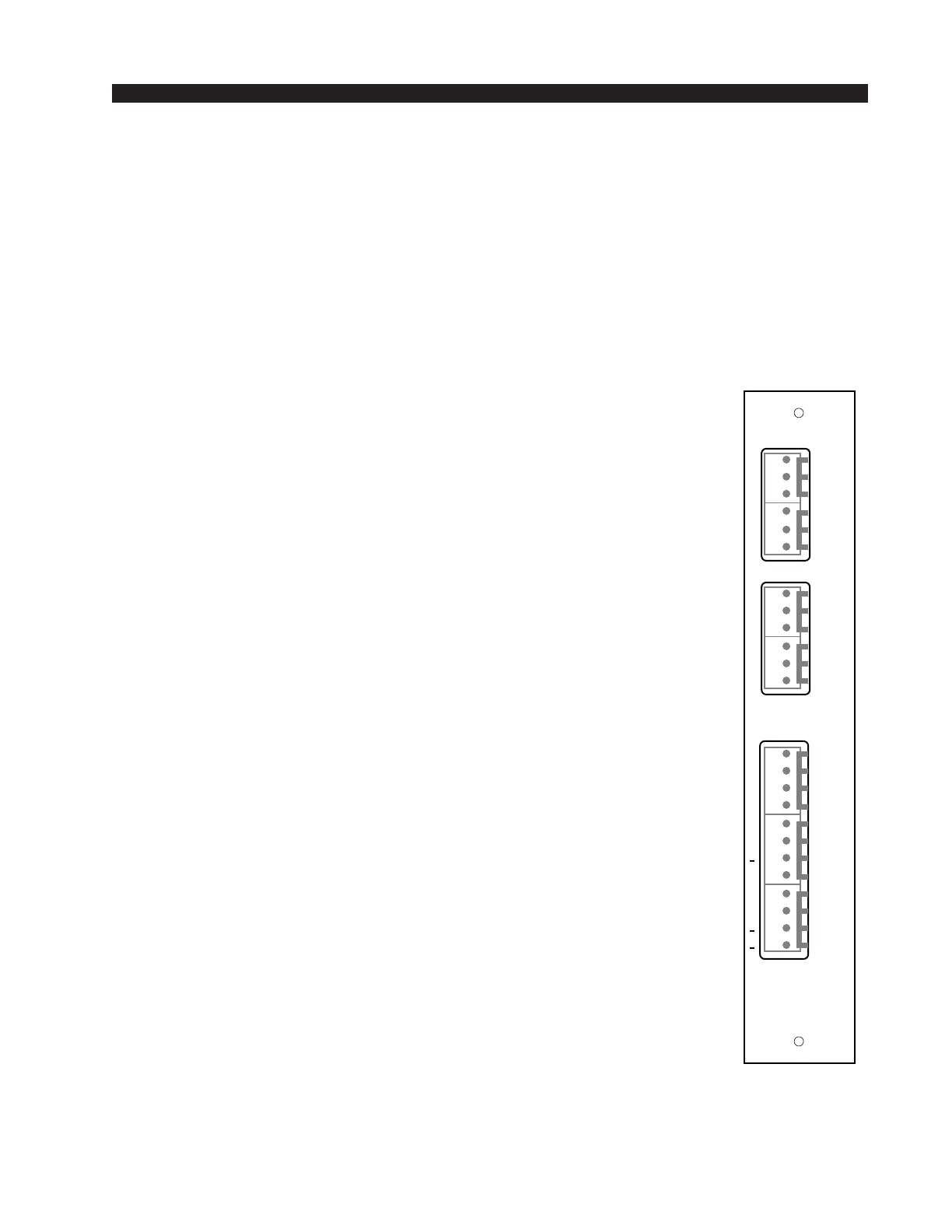
Stereo Line Analog Inputs
Audio Connections
These include A and B source inputs; level is +4dBu balanced.
Pin 6 – Line A In Lt LO
Pin 5 – Line A In Lt SH
Pin 4 – Line A In Lt HI
Pin 3 – Line A In Rt LO
Pin 2 – Line A In Rt SH
Pin 1 – Line A In Rt HI
Pin 6 – Line B In Lt LO
Pin 5 – Line B In Lt SH
Pin 4 – Line B In Lt HI
Pin 3 – Line B In Rt LO
Pin 2 – Line B In Rt SH
Pin 1 – Line B In Rt HI
LINE IN
IN A
L
S
H
IN B
DIG
TALLY
5V
S/S
OFF
STOP
OFF
START
ON
RDY
ON
RDY
LT
RT
L
S
H
L
S
H
L
S
H
LT
RT
C
B
C
+
+
+
+
+
+
1
2
3
4
5
6
7
8
9
10
11
12
1
2
3
4
5
6
1
2
3
4
5
6
We recommend a series
resistor between the LED
and +5V digital when you
are powering the external
tally from the console; a
value of 220Ω (1/4W 5%)
is suggested.
SLADC-70
Rear Panel