I N S T A L L A T I O N a nd P OWER
page 1 – 3
D-70 / Apr 2000
Modules and Rear Panels Layout
The D-70 console’s mainframe comes supplied with 12 or 20 input modules, a
control room module, a studio control module, and single and dual blank modules.
There can be optional modules: a superphone module, the two line select modules,
and a tape remote module. Each module type has it’s assigned slot (see drawing on
page 1-4).
The D-70 console also comes supplied with rear panels that are installed in the
following order (from right to left as viewed from the rear of the console): 12 or 20
any variation of MIC IN, LINE IN or DIG IN input panels, DIG IN or LINE IN panel
for EXT IN for switched meters, BLANK or optional CALLER panel, DIGITAL
OUT, ANALOG OUT, MONITOR1, MONITOR2, four BLANKS or optional
LINE SELECT panels, BLANK or TAPE REMOTE, and BLANK or optional EXT
SYNC panel. Rear panels layout see on the page 1-5.
Rear Panels Installation
To remove or install console’s rear panels you
must follow this procedure:
• Make sure the console is powered down.
• Open the meterbridge cover by removing the
two retaining screws on its rear lip.
• Open the meterbridge rear by removing the two
retaining screws on the upper lip. Then swing it
toward you until it rests in a fully opened position.
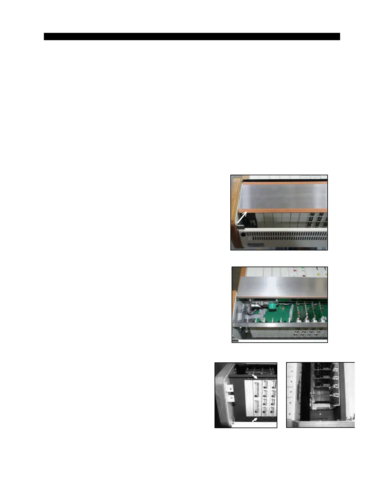
• Remove the shield panel’s tape (Figure 1),
being careful to avoid damage to the shield tape.
• Swing the shield panel to open (Figure 2).
• Disconnect the rear panel’s connectors.
• Remove the two phillips-head screws that hold
the rear panel in place (Figure 3).
• Unplug the rear panel’s card from the edge
connector by carefully pulling it up.
• Replace the rear panel, plugging in its edgecard
fingers to the appropriate motherboard edge con-
nector (Figure 2), and tighten down the two retain-
ing screws.
Make sure that you plug in the rear panel in its
appropriate slot!
• Replace the shield panel back reusing the
shielding tape.
• Close and secure the meterbridge rear and
cover.
Figure 1. Shield Panel.
Figure 3.
Rear Panels—Rear View.
D-70 / Feb 2002
Figure 2. Open Shield Panel.
Figure 4.
Rear Panels—Upper View