page 8 – 3
D-70 / Apr 2000
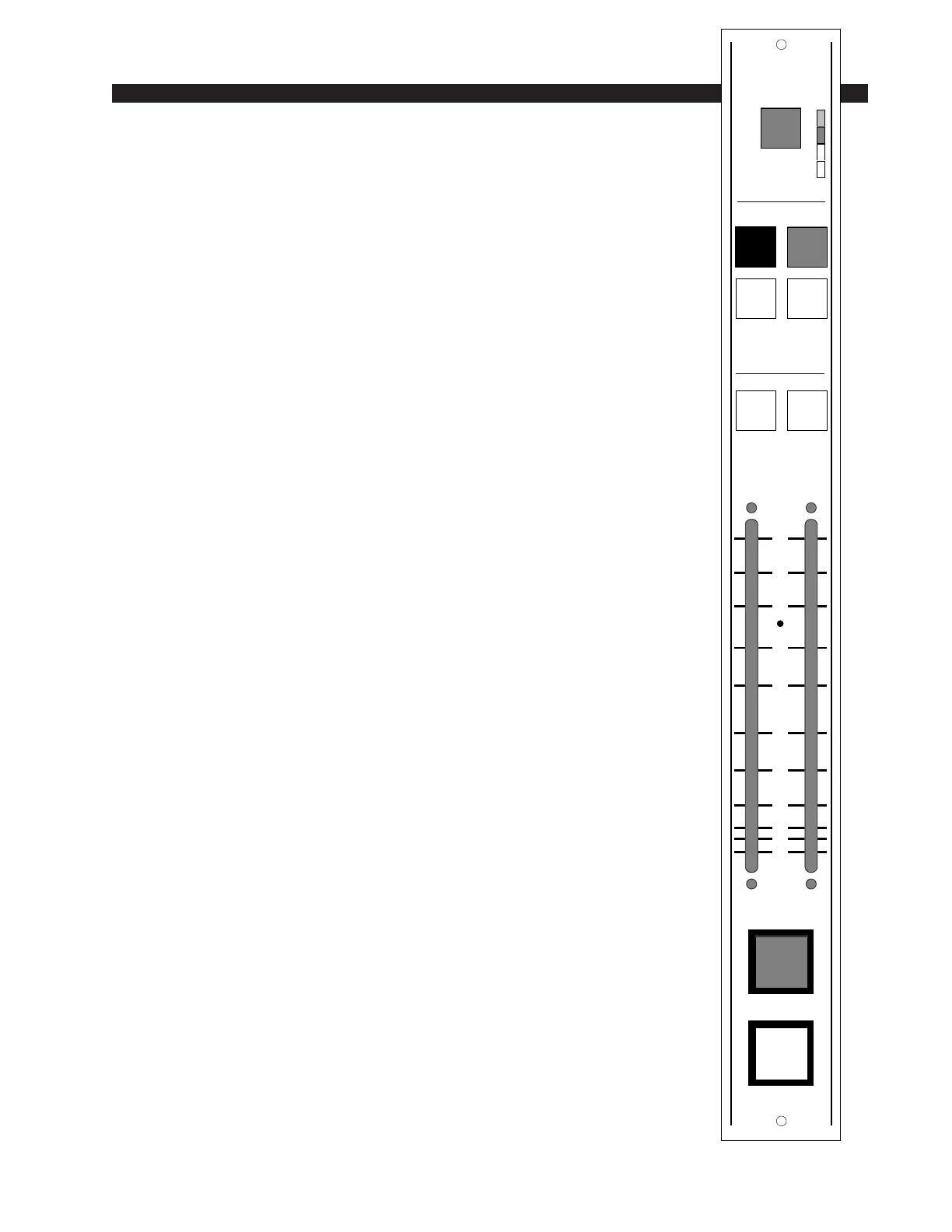
SUPERPHONE INPUT
Automatic Features
The channel ON (red) and OFF (amber) switches are at the bottom
of the module. These can be programmed (via internal PCB-mounted
dipswitches) to activate control room and studio mutes, tallies, and
timer restart.
Automatic cue dropout can also be programmed internally (page 8-
5), making it unnecessary to de-activate caller setup buttons before
going live; simply pressing the module’s ON switch will automatically
do this for you.
Inputs and Outputs
All audio and control signals hook-ups are made via four six-
conductor connectors mounted on the module’s rear panel. The upper
two connectors handles hybrid input signals (i.e., caller input) and the
caller 1 and 2 feeds to your station hybrid (the phone signals going to
your callers). The lower two connectors handle outputs that are
generally used for recording purposes:
Composite Out – This includes everything: DJ, callers, music beds,
etc. Generally used to to record phone segments in advance of actual
airplay.
Composite Minus Callers – This includes everything but the callers.
Callers Only – No talent, no DJs, no music; just caller voices.
Internal Programming Options
Internal programming is accomplished via seven printed circuit
board (PCB) mounted jumpers (J21, J22, J24, J25-J28), located on the
lower center of the Processing Board PR-70 PCB, and one PCB-
mounted slide switch (SW1), located on the upper center of PR-70
PCB. The SPIO-70 PCB card contains PCB-mounted trimpots which
may be used to set the module’s various output feed levels.
Cue Pre/Post
The module’s CUE signals (caller setup buttons 1 & 2) can tap pre
or post fader. When slide switch SW1 (upper center) is UP they are
PRE, when DOWN they are POST. (Factory default setting is PRE.)
0
5
10
15
20
30
40
50
70
00
60
CUE 1 CUE 2
PGM AUD
AUX1 AUX2
O
N
O
F
F
MXM
SOURCE
ASSIGN
CALLER
12
P
G
A
D
A
1
A
2
D-70 / Aug 2000