INSTALLATION and POWER
page 1 – 12
D-70 / Apr 2000
(2) The terminal conductor tabs (pointing UP) are
placed in anvil 18-22; the terminal's insulation tabs
extend in front towards the camera.
(3) The stripped wire is placed into the terminal and
crimped. Note the wire's insulation must stop just
short of the conductor tabs (detail)
HAND CRIMP TOOL WIRING INSTRUCTIONS
The supplied hand crimping tool (PALADIN model PA1645, W/S#850067) is used for
all I/O wiring connections to and from the console. It is to be used with the supplied
loose pin (figure 1) intended for 18"-24" gauge wire.
1) Strip wire approximately 3/16" (insert in
proper wire stripper, rotate one half turn, and pull
insulation off wire).
2) Leaving wire aside for the moment, with
Paladin tool fully open (engraved side toward you)
bring a terminal into position from the unmarked
side of the tool. Place the conductor tabs (inner
set as shown in figure 1) on the "18-22" or "24-30"
(depending on the wire) anvil (slightly curved
surface) so that the circular portion of the tabs
rests in the curved surface of the anvil and the two
tabs face up into the walls of the female jaw. The
insulation tabs will be flush with the top of the
tool (figure 2).
3) Close tool very slightly, only to the point of
holding the terminal in position (figure 2).
4) Insert wire into terminal until wire insula-
tion is stopped by conductor tabs (figure 3). CRIMP
by squeezing handles until jaws are fully closed.
5) If there is an insertion error or if a circuit
change is needed, you'll need to use an extractor
tool to remove terminals (next section).
(4) Final step: jaws fully closed; the insulation tabs
have been crimped.
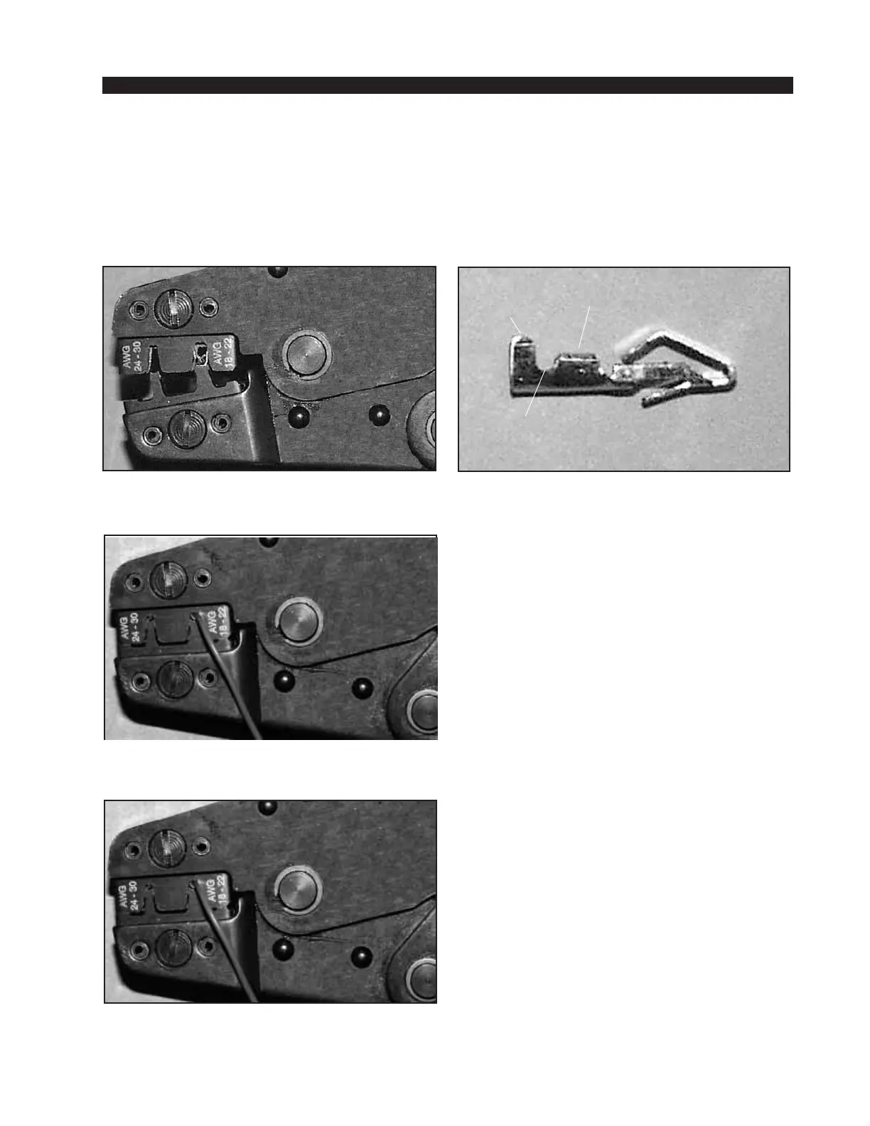
Insulation
stops here
(1) Pin crimp terminal
CONDUCTOR
TABS
INSULATION
TABS
INSULATION
STOPS HERE
page 1 – 11