page 2 – 4
D-70 / Apr 2000
INPUT MODULE
VDT Programming Options
Mutes, timer restart, cue dropout, local/ready, tallies, and auxiliary 2
bus pre-fader programming are made via Virtual Dip Switch Software (see
Chapter 6).
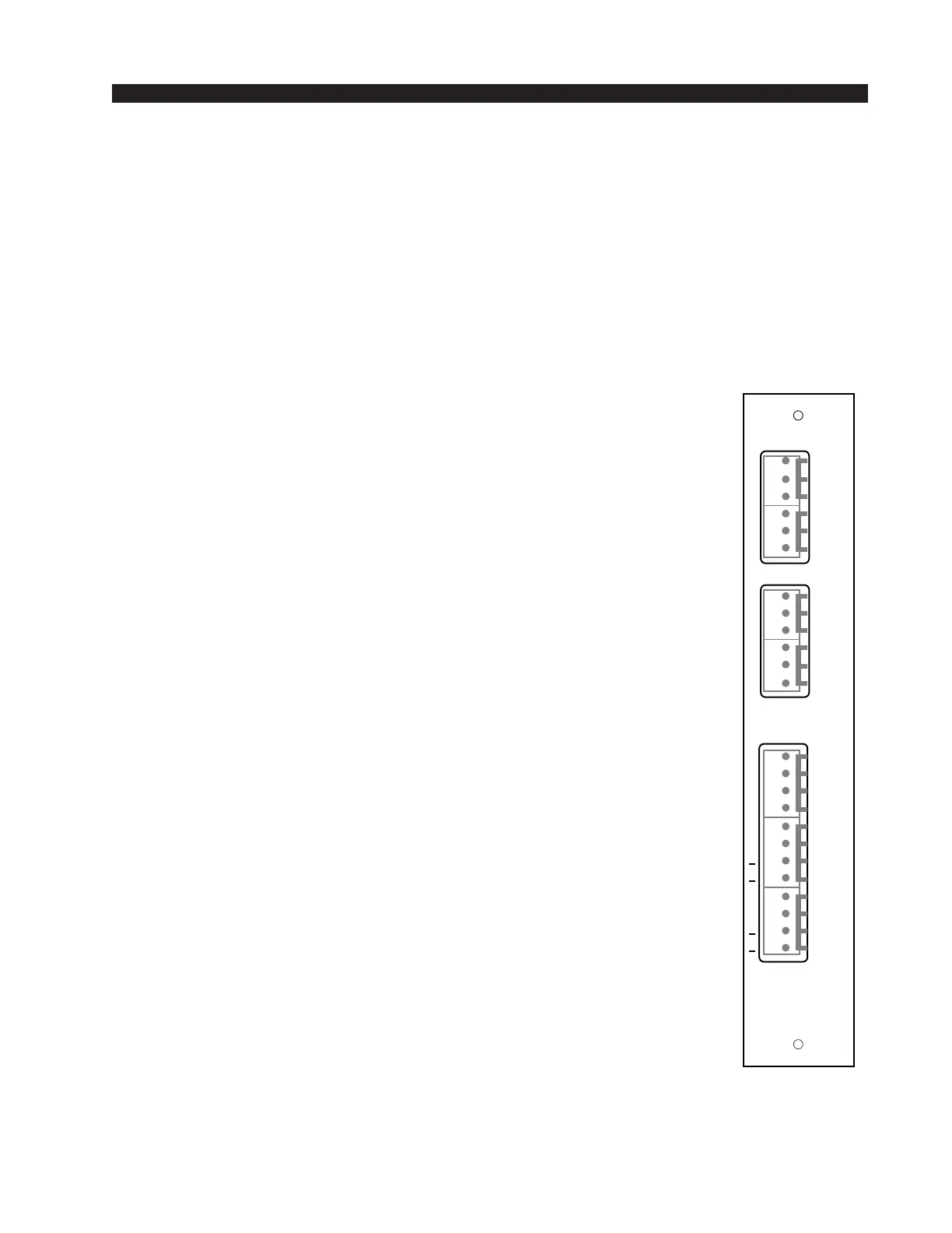
Hook-Ups
As stated before, all user wiring to and from IND-70 modules takes
place at six- and twelve-conductor connectors mounted on the module’s
rear panel. There are three connectors per module: two six-conductor
connectors handle audio signals; one twelve-conductor connector handles
control signals.
Microphone Inputs
Audio Connections
These include A and B mic inputs, and insert in and out. The mic input
level is nominally -50dBu. Insert points are +4dBu balanced in and out. All
signals are analog mono.
Pin 6 – Mic A In LO
Pin 5 – Mic A In SH
Pin 4 – Mic A In HI
Pin 3 – Mic B In LO
Pin 2 – Mic B In SH
Pin 1 – Mic B In HI
Pin 6 – Insert Out LO
Pin 5 – Insert Out SH
Pin 4 – Insert Out HI
Pin 3 – Insert In LO
Pin 2 – Insert In SH
Pin 1 – Insert In HI
Note the insert points are normally bypassed by PCB-mounted jumper
J1 (see page 2-3). The Insert Out pins may be used as a channel direct
output if desired.
Control Connections
These include remote on and off, cough, talkback and tally functions.
Note each function is available for A source port, allowing it to follow the
module's A mic selector switch.
Pin 1 – Cough
Pin 2 – TB to CR
Pin 3 – Off Tally
Pin 4 – On Tally
A
INS
DI
TALLY
B
5V
5V
DI
DI
N
FF
-
N
-
FF
TB
R
H
L
H
L
H
L
H
L
H
B
IN
OUT
IN
T
L
Y
+
+
MIC IN
1
2
3
4
5
6
7
8
9
10
11
12
1
2
3
4
5
6
1
2
3
4
5
6
MMADC-70
Rear Panel